Millwork is an integral part of any construction or renovation project, encompassing various wood-based components such as cabinets, countertops, moldings, and trim. For the efficiency and quality of millwork, precise and accurate millwork CAD drawings are necessary.
Millwork CAD drawings provide a comprehensive visual representation of the intended millwork components, including their dimensions, materials, and installation details. These drawings serve as a blueprint, enabling seamless collaboration among architects, designers, contractors, and fabricators.
In this guide, we’ll understand more about millwork CAD drawings, their standards, components, and the best tools for millwork drawings. So, let’s start!
What Are Millwork CAD Drawings?
Millwork CAD drawings are detailed, computer-aided design (CAD) representations of custom woodwork and architectural elements used in interior design and construction.
These drawings provide precise specifications for the fabrication and installation of millwork items such as cabinetry, moldings, doors, frames, and built-in furniture.
Generally, a draftsman or architect produces the CAD drawings of Millwork. These drawings outline every aspect of the millwork project, including dimensions, materials, finishes, and construction methods.
The digital format allows for easy modifications and ensures consistency throughout the project. These detailed plans are crucial for manufacturers and builders, as they reduce errors and streamline the production process.
Components Of Millwork CAD Drawings
These drawings include a variety of components to ensure precise fabrication and installation. The key components typically include:
Title Block
- Project Information: Name, address, client details, and project title.
- Drawing Information: Drawing number, date, scale, and sheet number.
- Designer/Architect Details: Name and contact information of the person or firm responsible for the drawing.
- Revisions: Record any changes made to the drawing with dates and descriptions.
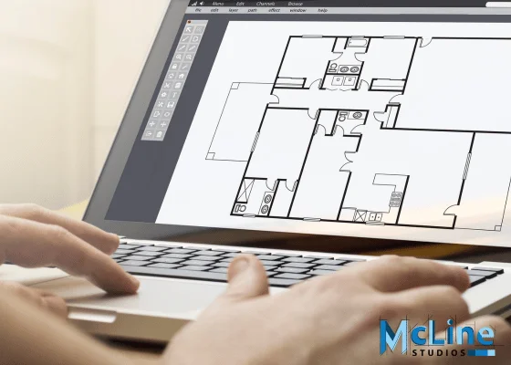
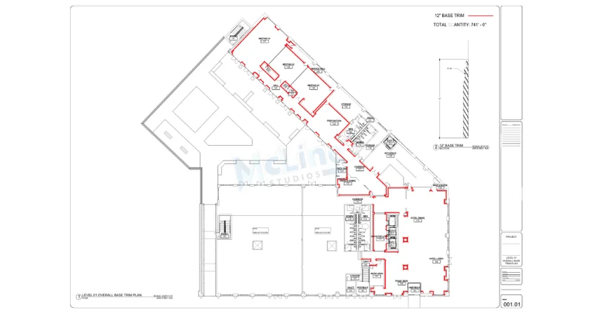
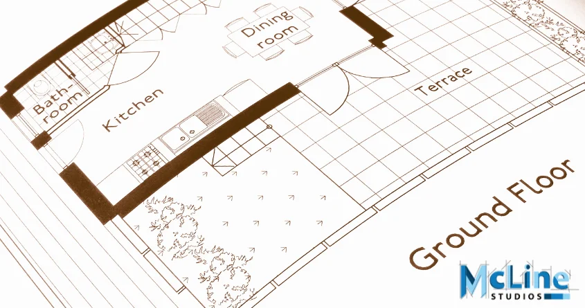
Plans
- Floor Plans: Overhead views showing the placement and layout of millwork elements in the context of the overall space.
- Reflected Ceiling Plans: Views showing ceiling treatments and details of any overhead millwork elements.
Elevations
- Front, Side, and Rear Elevations: Vertical views of millwork elements showing height, width, and depth.
- Interior and Exterior Elevations: Detailed views of built-in and free-standing millwork from inside and outside perspectives.
Sections
- Cross Sections: Cutaway views showing the internal structure and composition of millwork elements.
- Detailed Sections: Enlarged views of specific areas to show intricate details and construction methods.
Details
- Joinery Details: Specifications for joints, including type and dimensions.
- Trim and Molding Profiles: Detailed drawings of trim and molding shapes and sizes.
- Hardware Details: Specifications for hinges, handles, locks, and other hardware components.
Materials and Finishes
- Material Specifications: Detailed descriptions of the materials to be used, including wood types, veneers, and substrates.
- Finish Specifications: Information on stains, paints, varnishes, and other finishes to be applied.
Dimensions and Annotations
- Measurements: Precise dimensions for all components, including lengths, widths, heights, and depths.
- Notes and Annotations: Explanatory text providing additional information and instructions for fabrication and installation.
Schedules
- Door and Window Schedules: Lists detailing the specifications for doors and windows, including sizes, types, and hardware.
- Millwork Schedules: Comprehensive lists of all millwork components, including quantities and specifications.
Legends and Symbols
- Legend: Key explaining the symbols and abbreviations used in the drawings.
- Standard Symbols: Common symbols for elements like electrical outlets, switches, and lighting fixtures.
3D Views (Optional)
- Isometric Views: Three-dimensional representations of millwork elements to provide a clearer understanding of the design.
- Rendered Views: Realistic images showing materials and finishes for visualization purposes.
These components will make sure that millwork CAD drawings provide a complete and detailed guide for the construction and installation of custom woodwork projects, helping to avoid errors and ensuring high-quality results.
Latest Standards For Millwork Drawings
The latest standards for millwork CAD drawings primarily adhere to industry-specific guidelines and practices, ensuring consistency, precision, and ease of interpretation for both designers and manufacturers.
These standards encompass various aspects, including dimensioning, symbols, notation, and detailing.
One widely recognized standard is the Architectural Woodwork Institute (AWI) Quality Standards Illustrated (QSI). It provides comprehensive guidelines for the fabrication and installation of architectural millwork, covering everything from materials and finishes to construction methods and tolerances.
The QSI serves as a benchmark for quality and craftsmanship in the woodworking industry, facilitating clear communication between stakeholders and ensuring that projects meet established criteria for excellence.
Additionally, the American National Standards Institute (ANSI) oversees standards related to drawing practices, including ANSI/ASME Y14.5, which governs dimensioning and tolerancing.
Furthermore, industry-specific software tools like AutoCAD and Revit have become instrumental in producing millwork drawings, offering advanced features for precision modeling, annotation, and documentation.
While not standards per se, proficiency in these tools is often essential for modern millwork design and fabrication.
Best Tools For Millwork CAD Drawings
Tools help in creating millwork CAD drawings more accurate and precise. Here are some of the best tools for millwork CAD drawings, each with unique features that cater to different aspects of millwork design:
AutoCAD
AutoCAD by Autodesk remains a cornerstone in the CAD industry, renowned for its versatility and precision. It is a powerhouse tool that supports both 2D and 3D modeling, which is crucial for detailed millwork designs.
AutoCAD’s extensive libraries of pre-drawn objects and symbols provide a solid starting point for custom millwork projects, saving significant time and effort.
Its precision drafting capabilities ensure that every detail is precisely captured, which is essential in millwork where measurements need to be exact.
Revit
Revit, another powerful tool from Autodesk, is primarily known for its building information modeling (BIM) capabilities, making it an excellent choice for millwork projects within larger architectural contexts.
It excels in creating detailed and precise 3D models, which can be crucial for millwork designs integrated into broader architectural plans.
One of Revit’s standout features is its parametric modeling, which allows for easy modifications and adjustments throughout the design process.
This feature ensures that any changes in the design are automatically reflected across all related elements, maintaining consistency and accuracy.
Cabinet Vision
Cabinet Vision is a specialized CAD tool designed specifically for the woodworking and cabinetry industry, making it ideal for millwork professionals.
Its targeted features address the unique needs of this sector, offering tools that streamline the design and production process. Cabinet Vision excels in generating detailed cutlists and optimizing material usage, which helps reduce waste and increase efficiency.
Its integration with CNC machines facilitates automated production, ensuring that designs are executed precisely as planned.
Key Takeaways
To sum it up, millwork CAD drawings play a crucial role in the successful execution of custom woodwork projects. These detailed digital representations provide precise specifications, ensuring seamless communication between designers, manufacturers, and builders.
The use of specialized CAD tools like AutoCAD, Revit, and Cabinet Vision has become indispensable in the millwork industry. These powerful software solutions not only facilitate precise modeling and detailing but also offer advanced features tailored to the unique needs of woodworking professionals.