

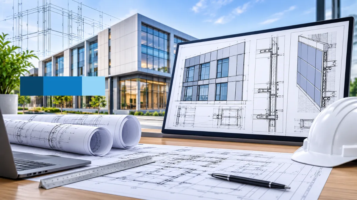
In the architectural elevations, wall panel systems may look straightforward, but when you pay close attention to wall panel systems, you will find several connected components that demand an intensive fabrication and installation process. Panel dimensions, support systems, joints, openings, flashings, and substrate conditions must work together. Without coordinating these elements before production, contractors may face incorrect panel sizes, installation conflicts, material waste, water-management issues, and costly site revisions.
Professional Shop Drawing Services translate architectural design intent into technical information for fabricators, contractors, and installation teams. For wall panel and cladding projects, drawings must give more than panel dimensions. Drawings must explain how panels connect, where panels terminate, how panels attach to the supporting structure, and how panels coordinate with building components.
A coordinated drawing package can include panel layouts, sections, connection details, fabrication information, and installation references. McLine Studios offers shop drawing support for construction projects that align with project requirements and the information supplied by the client. This article explains the detailing considerations for wall panel projects, including joints, substrates, openings, fabrication requirements, and installation interfaces. It also outlines what project teams should review before approving fabrication drawings.
Understanding the Role of Wall Panel Shop Drawings
The design intent is what architectural drawings primarily establish. This design intent is necessary for the overall appearance and general arrangement of a building. From panel layouts, elevations, material selections, to typical construction details, they show everything. However, component-level information, which is necessary for fabrication and installation, is missing.
The main purpose of Wall panel shop drawings is to develop the given information into coordinated technical documentation as per the project needs. Things that are included in the drawing package are:
- Panel layout plans and elevations are shown.
- Panel dimensions, identification marks, and orientation are listed.
- Horizontal and vertical joint details are included.
- Sections and through-panel assemblies are provided.
- Bracket, clip, rail, and attachment details are illustrated.
- Window, door, and other opening interfaces are shown.
- Flashing, corner, edge, and termination details are included.
- Material, finish, and panel schedules are listed.
- Fabrication and installation references are provided.
It is the panel system, material, requirements of the manufacturer, and scope of the contract that decide the level of detail in a project. Drawings should consist of the information that is needed by the team working on the project without interfering with the design or other responsibilities of the architects, engineers, or manufacturer.
Documenting the Complete Wall Panel Assembly
Shop Drawings that only showcase the visible panel face will miss out the important construction details and keep it unresolved. Therefore, clarity in wall panel placement depends on the components behind and around it. A wall panel is only a part of the exterior wall system.
A wall panel assembly can have:
- cladding panels.
- Panel clips, brackets, rails, or other support components.
- Structural support.
- Exterior. Backup wall.
- Weather-resistive barrier (WRB).
- Air and vapor control layers, if needed.
- Insulation.
- Drainage or ventilation cavity if necessary.
- Flashings, sealants, and perimeter closures.
The drawings need to show how the layers connect under conditions and during changes. For instance, a cross-section of a wall should display the panel support layout and the link between the cladding of the drainage cavity and the water-control layers. The exact assembly must follow the approved project documents and system requirements. It is not left to guesswork where a layer is, how thick it is, or what role it plays when the information is missing or contradictory. These unclear conditions should be noted for clarification before the affected details are finalized. When a project has façade systems, coordination with neighbouring trades is equally important. For example, the interface between wall panels and glazed openings should be checked against the glazing shop drawing and the approved system details.
Detailing Horizontal and Vertical Panel Joints
The appearance, alignment, movement, and weather-management strategy related to the panel facade is directly influenced by the joints. The coordination is really important across elevations and sections. It is not just treated as gaps that are present between adjacent panels.
Horizontal joints
When one panel course meets another, horizontal joints occur. So, drawings clarify:
- Joint and Alignment.
- Panel edge conditions.
- Supporting profiles or connection parts.
- Necessary. Space for movement.
- Flashing or drainage features if mentioned.
- Connection to floor lines, openings, and building face changes.
A layout that is consistent helps in maintaining the intended facade pattern. However, each panel system must align with the dimensions and coordinate in the right direction.
Vertical joints
Vertical joints and panel grids influence the facade’s overall appearance. In a drawing, panel width, joint locations, and alignment should be shown with architectural reference lines.
It is not compulsory that a layout that works on one elevation will go hand in hand with the other projects also. It may create narrow panels, misaligned joints, or difficult conditions for edges. For the facade that includes multiple elevations, the panel grid should be checked at building corners and transitions.
Movement and joint coordination
Exterior panels and the structures that hold them can expand and contract due to changes in temperature. How they can handle movement depends on the material used, how big the panels are, how they are supported, and how the whole system is designed.
Shop Drawings services should communicate the specified movement provisions and distinguish fixed points from sliding or adjustable connections where the system requires them. Do not assume that every joint or connection can accommodate movement in the same way. Confirm unresolved requirements with the responsible manufacturer or design professional.
Coordinating Substrates and Panel Support Systems
The positioning and installation of the panels can be directly affected by the material, condition, and geometry of the substrate. The substrate is responsible for providing the base on which the panel system is attached.
Different supporting conditions that are common include concrete, metal framing, structural steel, and other project-related backup wall systems. Each requires coordination with the specified attachment method.
A useful drawing package will identify:
- The substrate type and reference location.
- Bracket, clip, rail, or support positions.
- Attachment. Connection references.
- Required stand‑off dimensions.
- Adjustment provisions, where specified.
- Clearances around elements.
- Interfaces, with insulation and other wall layers.
Field verification and dimensional tolerances
It is not possible that design dimensions always match the existing site conditions. There may be changes in the concrete edges, alignment of the structural members, and existing openings that may differ from the architectural drawings. Before finalizing critical panel dimensions, project teams should establish which dimensions are based on approved design information and which have been field verified. Unverified dimensions should be clearly identified rather than presented as confirmed measurements. Where the substrate condition may affect panel alignment or bracket positioning, the drawing package should record the issue and request clarification. Effective Shop Drawing Services should help identify these coordination gaps before fabrication rather than simply reproducing dimensions from an incomplete drawing set.
Detailing Openings and Building Envelope Interfaces
Regular panel layout gets interrupted by windows, doors, vents, lighting fixtures, and service penetrations. Additional coordination should be needed at these locations because several trades and building components meet in a limited space.
Window and door interfaces
Opening details should address the head, jamb, and sill conditions. Depending on the specified system, the drawings may need to show:
The head, jamb, and sill conditions should be addressed in the opening details. A drawing needs to show (depending on specified systems):
- Panel termination and return dimensions.
- Frame-to-panel clearances.
- Flashing profiles.
- Sealant, backer requirements, where specified.
- Connection between the panel support system and opening framing.
- Coordination with the window or door system.
It is important to cross-verify the drawings against the approved opening schedule and available manufacturer information. Define the frame dimensions, perimeter clearances, and flashing requirements. If these details are not confirmed, then issues should be raised.
Penetrations and secondary components
Louvers, vents, signs, lighting fixtures, and other openings can change the size of the panels and where the support is required. The placement of these items must match the panel grid and the information from the trades. The set of drawings needs to show the size of each opening, where it is located, how the edges are finished, and any support or framing that is needed as part of the work that has been agreed on. Any problems with structure or waterproofing should be passed on to the responsible professional for the project.
Base, parapet, roof, and soffit transitions
Panel systems also come together with parts of the building at the bottom of the wall, the top of the wall, the parapet, the soffit, and the materials next to the facade. These conditions should need to be comprehensive so that the ends of the panels, the flashing, the covers and the water barriers can all work together. A drawing that stops at the edge of a panel without showing what is next to it can make it hard for people putting it up to understand a connection when they are on the job. Wall panel detailing should therefore cover the transitions that affect continuity, appearance, and installation.
Coordinating Weather Management, Fire Barriers, and Performance Requirements
For a more visible finish, exterior cladding details must be accounted for. Factors like water management, air and vapor control, insulation continuity, and fire safety provisions affect the overall wall assembly. For a rainscreen system, drawings should reflect the approved drainage and ventilation strategy. They should show the specified cavity arrangement, relevant flashing locations, and how the system interfaces with openings and terminations. The drawings should not introduce a drainage path or sealant arrangement that conflicts with the approved system.
Fire barriers and cavity barriers may also be needed inside wall assemblies. The places where Fire barriers and cavity barriers sit must line up with the approved fire and life‑safety documents and the product rules. The detailer should not decide on fire‑resistance ratings for Fire barriers and cavity barriers on their own.
Material compatibility is another consideration. Panel finishes, fasteners, support parts, sealants, and any nearby materials must be matched to the approved specs and the maker’s data. If any part of the Fire barriers and cavity barriers data is missing or clashes, bring it up for review.
Preparing Fabrication-Ready Panel Information
After the assembly and interfaces have been coordinated, the drawings must include all the information that the fabrication team needs. A single panel layout alone may not be enough for production.
Depending on the panel material and fabrication method, fabrication drawings may include Panel dimensions, panel identification numbers, material type, thickness, and finish references. With this information, fold, return, edge, and corner conditions should be noted; cutouts and openings must be specified; and hole and fixing locations are indicated, where needed, with panel orientation and face direction. Relevant schedules and detailed references are included.
Panel identification and schedules
Every panel should have a way to identify it. This way should connect the panels location, on the elevation to the panels making details. Panel marks must stay the same on all elevations, plans, details, and schedules. A panel schedule can contain the panel mark, size, material, finish, number, and drawing reference if the project needs it. If a panel is repeated, the drawings should make the repeated condition clear. Identify any variations.
Material and finish coordination
Fabrication methods change as per the selected panel materials. Also, edge conditions and installation requirements change depending on the panel material. Aluminum composite material, solid metal, fiber cement, wood, and other cladding products may have different detailing requirements. The drawing package should use the approved material and finish information. If the specification, schedule, and manufacturer data do not agree, the discrepancy should be resolved before production. A drawing should not silently substitute a material, finish, or fabrication method.
Planning Installation Sequence and Trade Coordination
Installation teams will be very benefitted with the panel drawing package that is completed and covers all technical ground. It helps teams to understand the arrangement used for the systems. The panel drawing package shows panel locations, reference lines, panel marks, and relevant sequencing notes in the installation drawings. The main aim of the panel drawing package is to make the relationship clear between the components and the overall facade.
Before finalizing the drawings, review the following:
- Panel installation direction and reference points.
- Starting locations and major alignment lines.
- Relationship between panel joints and floor levels.
- Access and clearance requirements identified by the project team.
- Coordination with glazing, roofing, waterproofing, and adjacent trades.
- Areas where inspections are required before components become concealed.
- Panel marks and references that match the fabrication schedule.
At the place where a wall panel facade meets aluminum-framed glazing or storefront system, it is important to coordinate opening dimensions, perimeter conditions, and installation sequence. The storefront shop drawings provide project teams with proper drawings to review these interfaces alongside the panel documentation. The installation sequence should reflect the actual project methodology and approved system requirements. If the sequence depends on access equipment, temporary works, or engineering decisions outside the drafting scope, those items should be confirmed by the responsible project team.
Common Wall Panel Drawing Mistakes to Avoid
Many recurring issues can be raised during fabrication or installation:
- Unverified dimensions: Using site dimensions that are not confirmed and not clearly marked as unconfirmed.
- Incomplete joint details: Showing where joints are located but missing information about edges, supports, or movement requirements.
- Missing substrate coordination: Detailing brackets without making sure the supporting construction is properly coordinated.
- Unresolved opening conditions: Leaving window heads, jambs, and sills without interface details that connect to surrounding elements.
- Inconsistent panel marks: Using different identification labels across elevations and schedules, causing confusion.
- Incomplete material information: Not including approved finishes, thicknesses, or product references for materials used.
- Unclear revisions: Allowing old drawings to stay in use after updates have been made, leading to misunderstandings.
- Uncoordinated trade interfaces: Not checking panel details against glazing, roofing, waterproofing, or other nearby systems, which can cause conflicts.
During drawing review these issues are easily addressed, once the materials have been fabricated or delivered to the site.
Pre-Fabrication Review Checklist
The project team can use the checklist before releasing a wall panel package for fabrication:
- Panel dimensions and locations match the layout.
- Panel marks remain consistent across elevations, details, and schedules.
- Horizontal and vertical joints are clearly defined.
- Movement requirements reflect the approved system information.
- Substrate conditions and attachment references are coordinated.
- Field-verified dimensions are distinguished from assumed dimensions.
- Window, door, louver, and penetration interfaces are detailed.
- Base, parapet, roof, soffit, and corner transitions are addressed.
- Flashing and water-management details reflect the approved assembly.
- Fire and cavity barrier interfaces are coordinated where required.
- Material, thickness, finish, and fabrication references are confirmed.
- Review comments and RFIs affecting fabrication have been resolved.
- Current revisions and release status are clearly identified.
For the project review process, contact requirements, and specific panel system, this checklist should be adapted.
Choosing the Right Drafting Support for Wall Panel Projects
Wall panel projects need information that works together across plans, materials, support systems, openings, and how they connect to other parts. A drafting partner should be able to use the project documents, the system details that are approved, and the agreed work scope to create consistent technical drawings.
McLine Studios offers shop drawing services for construction-related work including wall panels and cladding documentation. The work can involve panel layouts, connection and joint details, facade interfaces, and fabrication or installation information depending on the inputs provided and the needs of the project. For building-envelope-related work, project teams can also look into McLine Studios glazing shop drawing services and storefront shop drawings. These services can be important when a project needs coordination between cladding panels, glazed openings, and other façade components.
Conclusion: Coordinate Wall Panel Details Before Fabrication
Successful wall panel installation requires more than correct panel sizes. Joints, materials behind the panels, ways to attach holes for things like pipes or wires, layers that manage weather, and connections with trades all need to be planned before anything is made. Detailed drawings make it easier to check and talk about these details. They help the people who make the panels know what to build, give the people who put them up better guides, and let the whole team spot any issues before they cause problems on the job site.
By using Shop Drawing Services and following a structured review process, contractors and fabricators can improve the coordination of wall panel packages and reduce avoidable revisions during construction. To discuss a wall panel or cladding project, architectural drawings, scope of work, specifications, reference details, and project deadlines, contact McLine Studios.
Frequently Asked Questions
Wall panel shop drawings should show panel layouts, sizes, identification marks, joint details, support and attachment points, opening interfaces, material and finish data, and any fabrication or installation specifics. The exact details vary with the panel system and the project scope.
The substrate gives the base for the panel attachment system. Its material, location, and verified dimensions influence bracket placement, panel alignment, and connection coordination. Any unverified substrate conditions must be flagged for review.
Fabrication drawings give the dimensions, materials, edge conditions, and component data needed to make the panels. Installation drawings show where the panels go, how they connect, and other information needed for installing the system. Some project packages bundle both types of drawings.
Windows, doors, louvers, and other openings must be coordinated with head, jamb, and sill details, panel terminations, clearances, flashing, and interfaces with the opening system. Any missing or conflicting data should be clarified before the panels are released.
Only release drawings when all required project reviews and approvals are finished, and the information needed for the fabrication scope is fully coordinated. Any unresolved dimensions, material choices, connection needs, or interface questions must be solved before release.
Architectural drawings are a start, but more data may be needed. Depending on the project, this can include specifications, manufacturer system details, material and finish schedules, structural information, field measurements, and the contractor’s scope of work.