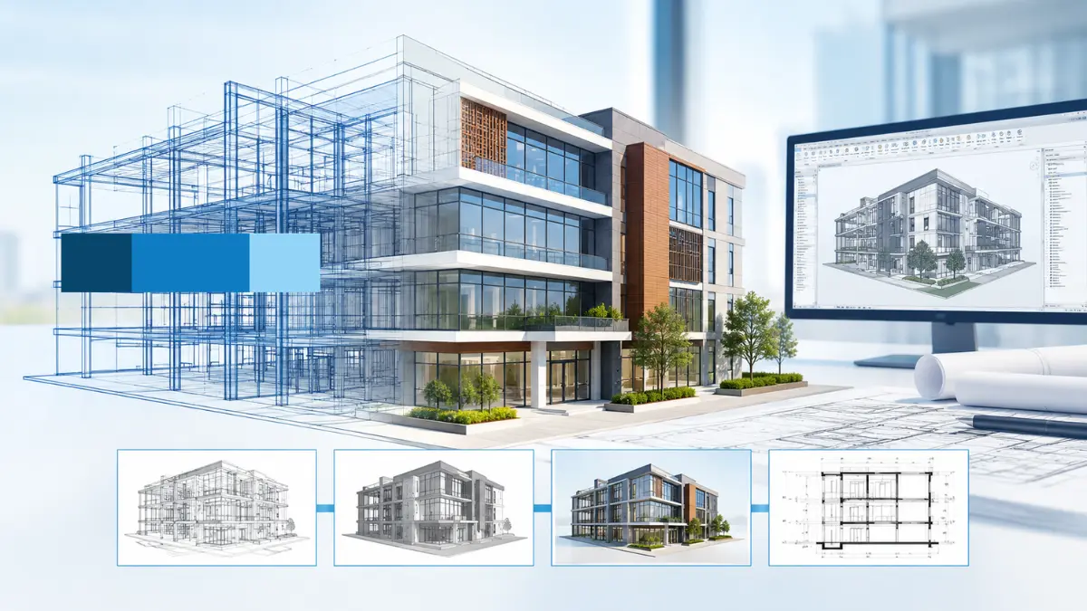
Ask 3 people on a project team what “detail” means in a Revit model, and you may get 3 different answers. An architect might talk about how a wall looks in a plan view. A BIM manager may refer to how much information is attached to it. A fabricator may talk about whether it is buildable. Each is related but distinct, and combining them often creates a large amount of preventable extra work.
This document provides information on Revit detail levels (Coarse, Medium, and Fine) and how they differ from BIM Level of Development (LOD 100-500). It describes what to define about the Revit model detail before constructing it. This information is designed to help achieve a real-world BIM Model, rather than simply a Revit model, and to address common assumptions. If you need support with modeling, Revit Modeling Services can help.
What Are Revit Detail Levels?
Revit detail levels in each view in Autodesk Revit allow settings of Coarse, Medium, and Fine. Each setting defines how much of the element’s geometry is displayed in that view. It doesn’t affect the element or the completeness of the model underlying it. It just controls what is shown to the user.
Families almost always include elements tied to these settings, meaning that geometry of doors, walls, beams, etc. can be drawn in a simplified manner at one level of detail and in a more graphically detailed manner at another level of detail. This is the basis for Revit detail levels and the control of the Revit view detail level. For more on these settings and their usage in production, see the Revit workflow modeling guide.
Coarse Detail Level in Revit
The Coarse detail level in Revit represents a more simplified model. Walls show up as thin lines with no texture and no layer lines. Elements represent a basic shape or symbol. The coarse level works well for things like Site Plan views and other large plan views, where adding a lot of detail, geometry, etc. is just clutter.
Medium Detail Level in Revit
The Medium detail level in Revit provides more geometric representation. This makes it the working level for general documentation. In addition to wall layers and door swings, Medium shows more detail for components and becomes the working level for documentation of many standard floor plans, reflected ceiling plans, and sections.
Fine Detail Level in Revit
The Fine detail level in Revit is the highest level of graphical representation. It can be used in large, enlarged plans, wall sections, and detailed views where layers, hatching, and component geometry are of importance to the viewer.
Fine is a display setting, not a quality setting. Setting a view to Fine will not develop the model further or make it more accurate or better for coordination, and it should not be used as a reason to over-model.
How Coarse, Medium and Fine Change a Revit View
The same element can appear differently in different views without any change to the model. Here are a few examples to illustrate Revit detail level settings:
| Element | Coarse | Medium | Fine |
| Wall | Single outline | Outline with layer lines | Layers, finishes, hatch patterns, and component detail |
| Door | Simple swing and opening | Frame, panel, and swing | Frame profile, hardware geometry, and trim, where the family includes them |
| Window | Basic opening symbol | Frame and glazing | Mullions, sill and head profiles |
| Structural framing | Single line or simple outline | Section shape outline | Full profile, with connection geometry if modeled in the family |
How a family behaves at different levels of detail depends on how the family was created. A family with no additional Fine level geometry will look the same at Medium and Fine levels of detail. Therefore, determining family visibility in Revit is as much a family creation question as it is a question of determining view visibility.
As a result, one Revit architectural model project can easily produce a clean, 1/16″ overall plan and a very detailed wall section of the same project at 1-1/2″. The element data stays the same. Only the way it is represented in a view changes.
Revit Detail Level vs. LOD: What Is the Difference?
Teams often treat these two terms as interchangeable, and they are not.
| Revit Detail Level | BIM LOD | |
| What it is | A view setting in Revit | A specification of model development |
| Scope | Applies to a view | Applies to a model element |
| Values | Coarse, Medium, Fine | LOD 100, 200, 300, 350, 400, 500 |
| Question it answers | How should this element appear in this view? | How developed and reliable is this element for its intended use? |
| Who controls it | Whoever sets up the view | The project team through the BIM requirements |
The main difference between Revit detail level and LOD is how much something can be relied on. The more detail the element is presented at, the higher the detail level. For example, a model element could be presented as Rough, like a brick wall, or Fine, like an aluminium wall. Detail Level has nothing to do with the element’s geometry, so an element with a certain amount of geometry, like a roughly shaped duct, could still be presented at Fine.
An element’s LOD is based on the amount of information defined by the modeler. A duct with an approximate size and location (LOD 200) is not reliable, but can still be presented at Fine. A very well-coordinated, positioned, and re-cropped beam (LOD 350) is not reliable and shouldn’t be presented at fine. However, in an overview plan, the beam could be presented at Coarse.
So, the difference between Revit detail level and LOD relates to different aspects of an element. Higher Detail Level does not always mean higher LOD.
Understanding LOD 100 to LOD 500 in a Revit-Based BIM Workflow
LOD in BIM describes most uses of LOD in BIM. The AIA was an earlier contributor. LOD standards in BIM are usually implemented per element and per discipline.Each team adapts LOD standards as part of the BIM execution plan.
LOD 100: Conceptual
Elements are indicators of potential size, shape, and location, and can convey existence in loose and generalized terms. It is particularly effective for conveying early feasibility and concepts.
LOD 200: Approximate Geometry
Size, shape, location, and quantity of elements are modeled by approximate systems. It helps in early-stage design development and rough coordination.
LOD 300: Precise Design Geometry
Each element is precisely sized, shaped, positioned, and oriented. This typically supports design documentation and design coordination. It also describes how the design intent is to be built.
LOD 350: Coordination and Interfaces
Elements add interfaces with other systems such as supports and connections, so trades can specify how components connect. In a discussion of Revit LOD 300 vs 350, the main difference is about these interfaces.
LOD 400: Fabrication and Assembly
Elements are fabricated with enough information for assembly and installation and are tied to trade means and methods; thus, they are not defaults for every element.
LOD 500: Field-Verified
LOD 500 represents aspects validated against on-site construction. It is not just adding more detail. It expresses verification, which is the reason it is connected to the as-built model instead of the development of the design.
Turning drawings or scan files into a working model usually starts a reliable BIM workflow, and CAD to BIM services provide the foundation for that workflow.
LOD 400 is not necessarily required for every project, and LOD 300 is not always sufficient. The highest LOD that would be effective is the required LOD for the use case. Some models may contain too much detail for the use case.
Why Teams Need to Define Detail Requirements Early
Without clearly defined BIM model details at the outset, teams default to guesswork, which often leads to:
- Over-modeling: adding extra geometry that no one uses, but slows the model down and can burn hours.
- Under-modeling: overly vague elements that cause field clashes during construction.
- Model performance issues: heavy, large files that slow down the process of working with the model.
- Coordination risks: different trades assuming different levels of reliability.
- Rework: requiring remodeling and redrawing due to poor modeling and late discoveries.
The goal should be to model only to the level of detail necessary for the intended use of the model for a given stage of the project. Intended use can vary and can include design visualization, quantity take-off, clash detection, and construction documentation, to name a few.
What Should Be Defined in a Revit/BIM Modeling Requirement?
An effective requirement defines answers to a short list of questions. Whether you refer to it as a BIM model specification or part of the BIM Execution Plan, it should define the following:
Project phase: Each of schematic design, design development, construction documents, and the construction phase (including the as-built).
LOD: The required level for each of the element categories for each of the phases.
View detail: The setting of the Coarse, Medium, and/or Fine filter for each view type
Elements: Which elements are modeled and which elements remain in 2D drawings and notes.
Information: The parameters, classification, and/or data for each element.
Requirements for coordination: Who models what, the frequency of sharing models and/or resolving clashes.
Define LOD by Discipline and Element
There should not be a single universal LOD for the entire project. Structural framing may require LOD 350 for certain types of coordination, and interiors may remain at LOD 200. It is better to specify by discipline and element, in order to focus effort where it is rewarded.
Set Revit Detail Level Settings for Views
Detail Level should appear in view templates and drawing standards. Agree on which view types use Coarse, Medium, or Fine, in order to keep drawings consistent across the sheets. Separate this from the LOD table.
How Detail Requirements Change Across Architecture, Structure and MEP
Different aspects of a Revit Construction model are required for different disciplines.
Architecture: Early in the process, walls, doors, and windows may be placed with placeholder materials, and interiors may be faux-finished. Later, wall and other materials’ finishes, as well as openings, need to be defined. Interior and exterior finishes and surfaces, facades, and materials may all be defined.
Structure: Sizes and locations of members may vary throughout the process, and connection-level detail may not be required until fabrication.
MEP: As in the other disciplines, sizes and placement of members may be defined throughout the process, and connection-level detail defined at varying stages. Teams that need drafting support across these systems can look at MEP drawing services for coordinated documentation.
A model adequate for design visualization is completely different from a model adequate for construction coordination, and a model adequate for construction coordination is completely different from a model adequate for fabrication.
Common Mistakes Teams Make
- Considering Detail Level and Level of Development as the same thing. Setting a view to Fine doesn’t increase an element’s LOD.
- Using a single LOD for everything. This wastes effort on low-impact elements and limits high-impact elements.
- Modeling too much too early. Detail modeled before a decision is finalized is likely to be changed.
- Concentrating on geometry only. Data in parameters is as important as geometry for the quantity and coordination of elements.
- Not defining deliverables. Without defined deliverables, teams can’t tell when the model is complete.
- Not setting Detail Levels for each View. Different Detail Levels set result in uneven-looking sheets even if the model is correct.
Practical Revit Detail-Level Checklist
Before Modeling:
- Make sure the project phase and intended uses of the model are confirmed.
- Identify the LOD (Level of Development) required by element and discipline.
- Identify which elements of the model will be included.
- Identify the information and parameters required.
- Establish Detail Levels for the various view types.
- Agreement on rules of coordination and deliverables.
- Confirm the review process and standards.
Before Delivery:
- Check the LOD table and ensure the geometry matches the LOD.
- Verify the information is complete.
- Conduct a coordination check.
- Review Detail Levels for various views.
- Check the performance of the model.
- Document any exceptions to the LOD.
How Revit Modeling Supports Better BIM Coordination
A well-defined Revit BIM model provides a consistent reference frame for all disciplines. This establishes a foundation for BIM model coordination, supports clash prevention across all disciplines, and helps maintain design intent in the documentation. It provides a framework for downstream quantity-related workflows and documentation.
Models at the appropriate level of development support fabrication. The further the model development level, the stronger the base to support shop drawing services. The geometry model is sufficiently described to permit fabrication. This assurance is especially important when model intent is used to provide the foundation for services.
When Should Teams Consider Outsourcing Revit Modeling?
There are several reasons why outsourcing BIM makes sense. It can help with large and multidisciplinary models, heavy workloads, and when the in-house team is stretched thin. It’s also a good option for projects that begin with CAD or PDF files, and for projects that have intense scheduling conflicts and deadlines.
At McLine Studios, we help U.S. based architects, Engineers, and VDC Teams throughout the entire documentation process, including Revit model creation, CAD drafting, MEP drafting, BIM coordination, shop drawings, permit sets, and construction documentation. With our BIM outsourcing services, you have the flexibility to quickly and easily scale your workforce to meet the demands of your project, without dealing with the added stress of juggling multiple outsourcing vendors.
Conclusion
Revit detail levels are used to control how elements are represented in a view. In contrast, LOD defines how developed and reliable an element is for its intended use. It is best practice for the architecture and construction teams to determine both (phase, discipline, and element) early on in the process to define how the model should behave. This helps keep the model usable and reduces the need for rework. Ultimately, this helps to streamline coordination of BIM processes.