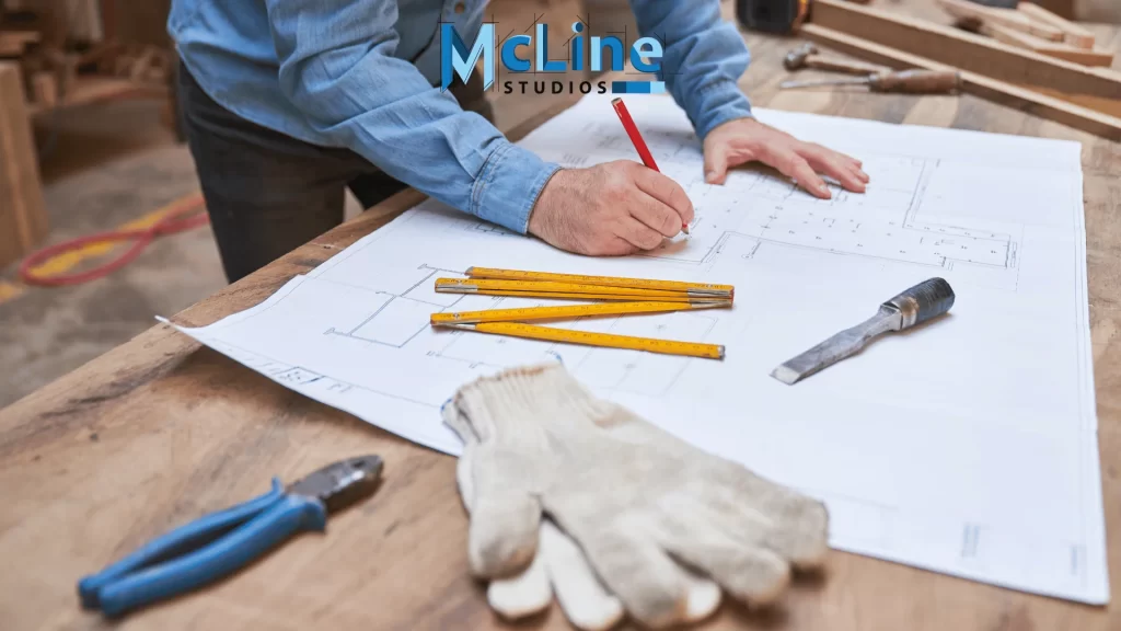
Construction drawings, also known as blueprints or architectural drawings, are detailed illustrations and plans that are used in the construction industry to guide the construction or remodeling of buildings, infrastructure, and other structures.
They are precise, scaled diagrams that provide a comprehensive visual representation of a building project, guiding every aspect of the construction process.
Before breaking ground, a wide array of construction drawings must be precisely prepared, each serving a specific purpose and conveying critical information. These diagrams depict the overall design, structural elements, material specifications, utility layouts, and intricate details that transform a concept into a real functional structure.
Whether you’re an architect, contractor, or simply fascinated by the construction process, understanding the major types of construction drawings is essential. In this article, we’ll explore the various categories of these diagrams, and their unique purposes in the successful completion of any construction initiative.
Architectural Drawings
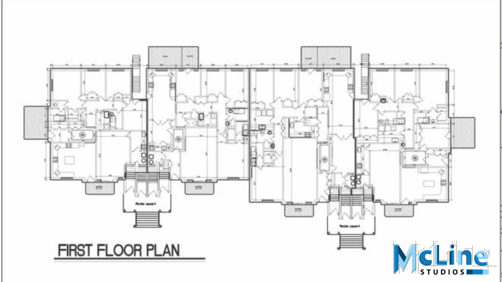
Architectural drawings are technical drawings and diagrams created by architects, engineers, and designers to illustrate and communicate the design and details of a building or structure. They are typically created using standardized symbols, scales, and conventions to convey information accurately and efficiently.
Purpose
The primary purpose of these drawings lies in communicating the architect’s vision to clients, contractors, engineers, and other stakeholders involved in the project.
They represent spatial relationships, dimensions, materials, and other essential aspects, enabling informed decision-making and ensuring alignment with the desired outcome.
Moreover, architectural drawings serve as legal documents, forming the basis of contracts and permits. They facilitate compliance with building codes, zoning regulations, and safety standards, thereby ensuring the structural integrity and functionality of the built environment.
Shop Drawings
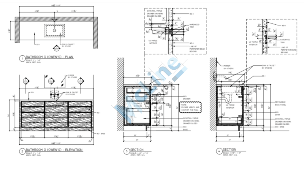
Shop drawings are detailed drawings, diagrams, or plans created by contractors, subcontractors, manufacturers, or fabricators to illustrate how specific components or parts of a building or structure will be fabricated, installed, or assembled.
These drawings are typically created based on the architectural, structural, and engineering drawings provided by the architect or engineer of record.
Purpose
Shop drawings are detailed illustrations or diagrams created by architects, engineers, or contractors to communicate specific design and construction details to manufacturers, fabricators, and construction teams.
These drawings provide crucial information regarding dimensions, materials, assembly, and installation instructions for various components of a building or structure such as structural steel, concrete reinforcement, mechanical systems, electrical systems, plumbing, millwork, and other architectural components.
Their primary purpose is to ensure accurate fabrication and construction according to the intended design, helping to minimize errors, streamline production processes, and ultimately facilitate the successful execution of construction projects.
Structural Drawings
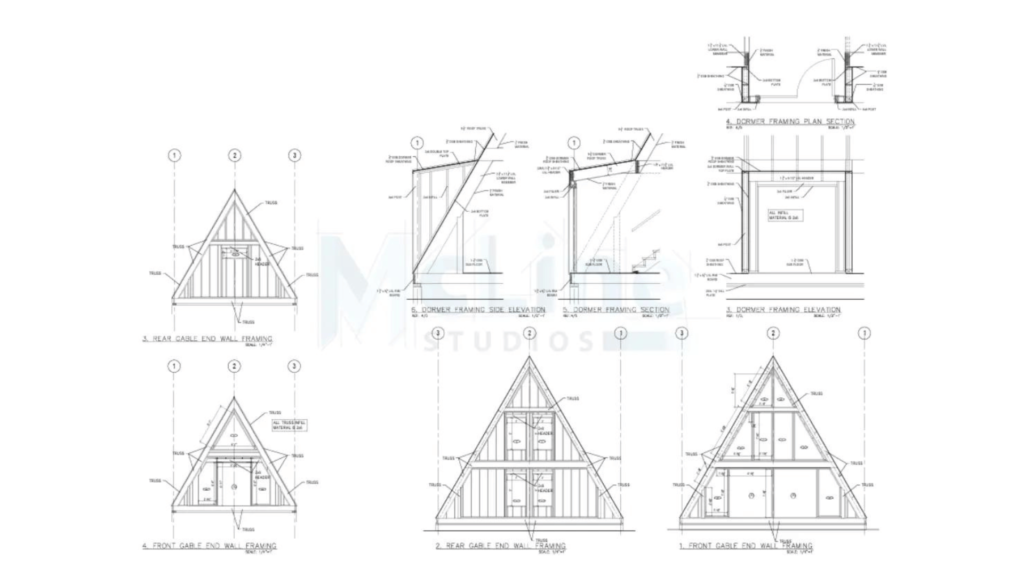
Structural drawings are detailed diagrams or plans that depict the structural components and systems of a building or structure. These drawings are essential for architects, engineers, and builders to understand how a building will be constructed and to ensure that it meets safety and stability requirements.
Purpose
Structural drawings serve as detailed blueprints for construction projects, outlining the structural elements necessary to ensure the stability, safety, and durability of buildings or infrastructure.
They provide important information to architects, engineers, and construction teams, illustrating the arrangement and dimensions of beams, columns, walls, foundations, and other load-bearing components.
These drawings convey critical details such as material specifications, reinforcement requirements, and connection methods, facilitating precise construction according to design specifications.
MEP Drawings
MEP drawings, short for Mechanical, Electrical, and Plumbing drawings, are detailed plans and diagrams used in the construction and engineering industries. They provide a comprehensive layout of the mechanical, electrical, and plumbing systems within a building or structure.
Here’s a breakdown of what each component typically includes:
- Mechanical: This part of the drawing focuses on the heating, ventilation, and air conditioning (HVAC) systems. It includes details such as ductwork, HVAC equipment placement, exhaust fans, and any other mechanical systems necessary for climate control and air quality within the building.
- Electrical: The electrical portion of MEP drawings covers the placement and routing of electrical wiring, outlets, switches, lighting fixtures, circuitry, and other electrical components. It also includes specifications for the electrical distribution system and any backup power systems like generators or batteries.
- Plumbing: The plumbing section outlines the layout of pipes, fixtures, drains, and other plumbing components. This includes water supply lines, sewage lines, drainage systems, fixtures such as sinks and toilets, as well as any specialized plumbing systems required for the building, such as fire suppression systems or medical gas systems.
The primary purpose of MEP drawings is to illustrate the layout, design, and specifications for mechanical, electrical, and plumbing systems within a building or construction project. They ensure proper coordination, installation, and functionality of these critical building systems.
Site Plans
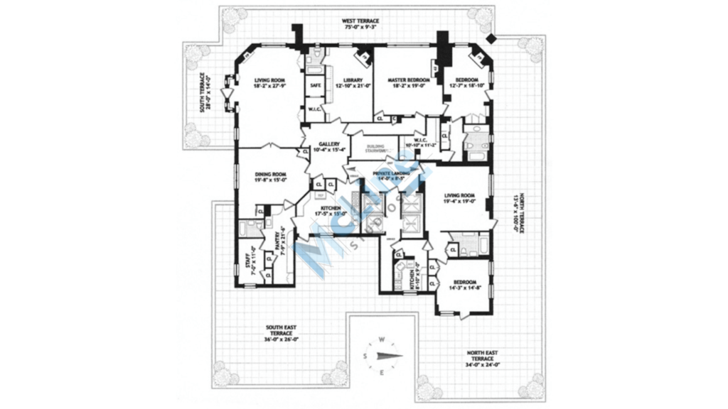
Site plans are detailed diagrams that showcase the layout of a property or development project. They provide essential information about the arrangement of structures, landscaping, utilities, and other features within the site boundaries.
These are typically created by architects, engineers, or urban planners, site plans are crucial for obtaining permits, zoning approvals, and ensuring compliance with building codes and regulations.
Purpose
These plans offer a bird’s-eye view of the site, indicating the positioning of buildings, parking lots, access roads, green spaces, drainage systems, and any other relevant elements.
They help stakeholders visualize the proposed project and understand how it fits into its surroundings, facilitating effective decision-making and communication throughout the development process.
Interior Design Drawings
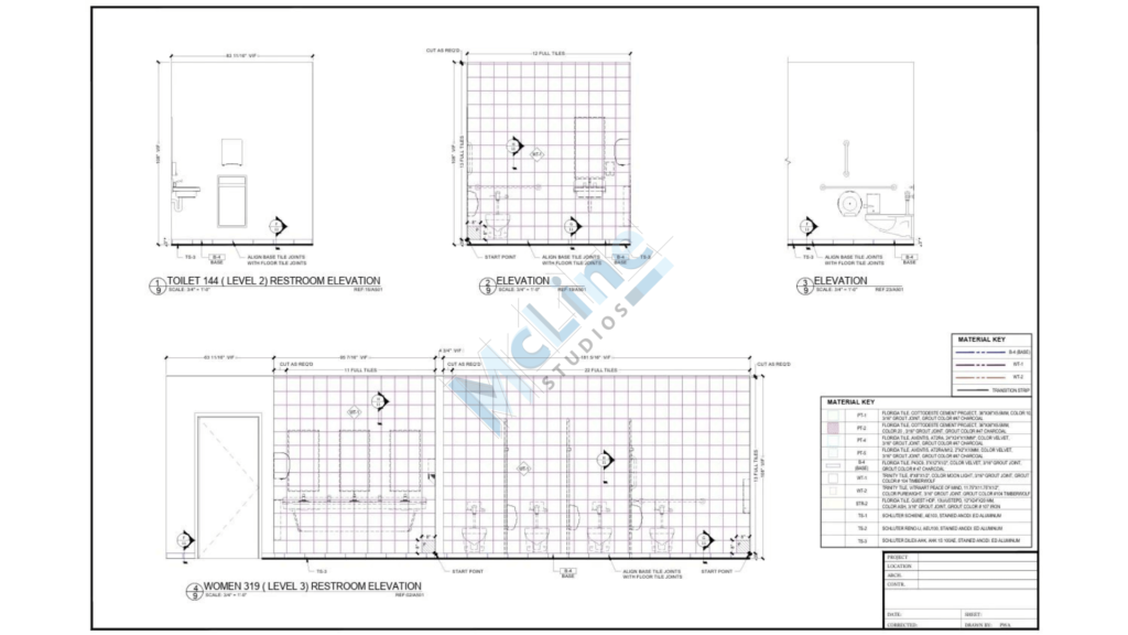
Interior design drawings are visual representations created by designers to convey their ideas and plans for a space. These drawings can include floor plans, elevations, sections, and perspectives, providing detailed information about the layout, dimensions, materials, and furnishings of a room or building interior.
Purpose
Interior design drawings visually communicate design concepts, spatial layouts, and decorative elements for architectural spaces.
These drawings aid in conveying ideas to clients, architects, and contractors, ensuring clarity and accuracy in the execution of interior design projects. They encompass floor plans, elevations, sections, and details, facilitating effective collaboration and bringing design visions to reality.
Detail Drawings
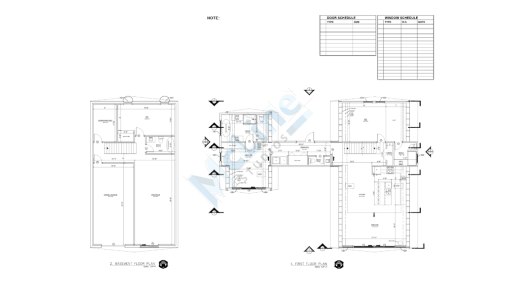
Detail drawings are comprehensive and precise graphical representations used in engineering, architecture, and construction industries to convey specific information about a component, assembly, or part of a structure.
These drawings provide intricate details such as dimensions, material specifications, surface finishes, and tolerances necessary for manufacturing or construction purposes.
Typically created from larger-scale drawings or models, detail drawings explain complex features, connections, and relationships within a design, ensuring accurate fabrication and assembly.
Purpose
They serve the crucial purpose of providing specific information and specifications about components or parts within a larger project or design.
They offer comprehensive guidance to manufacturers, engineers, or construction workers, ensuring accurate replication of complex structures, dimensions, and features, thereby facilitating precision and efficiency in the production process.
Civil Drawings
Civil drawings are technical illustrations and plans used in civil engineering projects to communicate design details and specifications. They typically include layouts, elevations, sections, and details related to structures such as buildings, roads, bridges, and infrastructure.
These drawings serve as a visual representation of the project’s components, dimensions, materials, and construction methods. Civil drawings are essential for conveying the architect’s or engineer’s intent to various stakeholders, including contractors, clients, and regulatory authorities.
Purpose
Civil drawings serve the crucial purpose of visually communicating the design and specifications of civil engineering projects. They provide detailed plans, elevations, sections, and other graphical representations to convey the layout of structures, dimensions, materials, and other essential elements.
Civil drawings are indispensable for guiding construction teams, ensuring accurate implementation, and facilitating effective communication among stakeholders throughout the project lifecycle.
The End Note
To sum it up, understanding the major types of construction drawings is essential for anyone involved in the building process, from architects and engineers to contractors and construction workers. Each type serves a specific purpose and provides crucial information that guides the entire construction project.
Starting from the conceptual stage to the final execution, these drawings communicate design intent, technical specifications, and construction details. Whether it’s architectural drawings, structural drawings, MEP drawings, or others, they all play a vital role in ensuring clarity, accuracy, and efficiency throughout the construction process.

