
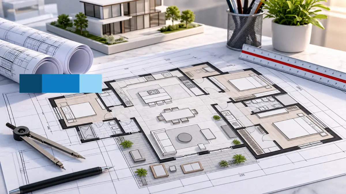
A good floor plan shows where walls and rooms are, but a great floor plan communicates much more. Great floor plans show dimensions, openings, circulation, and other information that project team members need to coordinate design elements. Inconsistent commercial floor plan drafting results in confusing or misaligned layouts, design conflicts, and costly changes to drawings. Floor Plan Drafting Services provides production support to teams that need it.
This article reviews the principles of a comprehensive commercial floor plan drawing, explains the reasoning behind each of the aforementioned elements, and identifies potential errors that would require a drawing to go back to the coordination stage. It also reviews how the floor plan must respond to the type of building it represents, and how the elements must align with architectural floor plan drafting in a set. It covers the most common mistakes that lead to rework, and how designers and architects must strike a balance between function, form, and fashion.
What Is a Commercial Floor Plan Drawing?
A floor plan is a drawing that shows a horizontal view of one level of a building as if the building had been cut roughly at window height. A commercial building floor plan shows the level’s organization, including walls, openings, and circulation as well as fixed elements. What is included in a commercial building floor plan depends on its purpose and the stage of the project. For example, a plan drawn to express a particular idea early in the project contains less information than a plan produced for coordination.
How commercial floor plans communicate building layouts
Architects use plans to test out different layouts. Developers use them to assess leasable or usable space. Contractors use plans to understand what is being built and where. For all three, plans are the central point of reference for other documents. That’s why plans are the foundation of commercial architectural drawings for commercial projects.
Floor plans versus reflected ceiling plans, site plans, and life-safety plans
A floor plan is only one type of architectural drawing. A reflected ceiling plan is another. These drawings illustrate layouts of ceiling materials and ceiling-mounted items. A site plan places the building on the property. A life safety plan is a drawing illustrating code-related info and egress. While a general floor plan shows some information related to these items, it is not a substitute for the drawings. A floor plan that contained info from all the related drawings would be long and cluttered. Knowing the boundaries of the dedicated drawings helps keep a floor plan legible.
Essential Elements Every Commercial Floor Plan Should Include
Here are nine essential elements of a commercial floor plan. For each, we cover what is shown on the drawing, the rationale, and what to look for.
1. Drawing identification and sheet information
Every drawing must contain the project name, drawing title, the level or floor (if applicable), sheet number, issue date, revision information, scale, and the title-block fields your standards require. Including this information enables the user to identify the correct drawing and determine if it is the latest revision. Drawings without a clear revision trail make it likely that a user will base work on an obsolete revision.
Check: Does the title block match the sheet index? Scale stated and consistent with graphics?
2. Overall and internal dimensions
Drawing dimensions are authoritative. Final plans show building and room dimensions, wall offsets, clearances, and organized dimension strings. Dimensions shown in commercial floor plans follow a consistent reference system, i.e., gridlines or face of stud, so readers can identify where each measurement begins and ends. Conflicting or repeated dimensions are the quickest way to create confusion in the field.
The ability to accurately dimension also depends on the drafting technicians’ ability to produce clean digital drawings. A disciplined base file with the use of layers, templates, and styles consistent with the firm’s standards is the basis for annotating floor plans. CAD Drafting services provide this foundation. Architectural drawing annotation standards lay the foundation for dimension strings, graphic parameters, and title block information.
Check: Are dimension strings accurate, and do they add up to the overall dimension?
3. Exterior walls, partitions, and structural references
Plans should differentiate between walls, partitions, and other fixed elements (e.g., shafts, columns, etc.). The thickness of walls is important for layout and space, as well as the placement of other trades. Structural grids and column locations should be provided for reference.
One key point: A floor plan should reference structural elements, not represent structural design. Sizing and detailing should be left to the structural engineer.
Check: Does the given floor plan align with the existing structural drawings in terms of grid lines and column locations?
4. Doors, windows, and other openings
Locations of openings should be shown along with identification tags and swing direction, as relevant, and references to the applicable schedules. Where a door tag on the plan does not agree with the door schedule, the contractor stops and asks. Consistent tagging is a small effort that prevents repeated requests for information.
Check: Does every tag on the plan agree with the applicable schedule?
5. Room names, functions, and space identification
Names and numbers in the plan tell the reader the function of the space. The name of the space often appears on several different sheets. Meeting rooms often appear on finish schedules and area calculations. The same room can also be depicted in many places on various sets of plans and drawings. This is why it is important to be consistent. If the name is not consistent, it creates confusion and a misunderstanding of what the space is being used for.
Check: Is the name and number of the room consistent on the plan and throughout the schedules that reference the room?
6. Corridors, circulation, stairs, and elevators
The plan should show the main circulation paths, access points, stairs, and elevators. It should show and explain the movement between spaces and connections. Circulation graphics help the reviewers to understand the user movements through the building. The paths should meet the requirements of egress and other codes. The plan should show the information in a clear and easy-to-understand manner to allow the check against the criteria to happen.
Check: Can a reviewer trace a path to all exits, elevators, and stairs from all the occupied spaces without having to guess?
7. Accessibility and life-safety information
Plans may contain information about accessible routes, door clearances, and other information about accessible facilities, exits, and rated partitions, if those items fall within the drawing scope. A general architectural floor plan typically isn’t a substitute for a dedicated life-safety plan or accessibility plan. The scope of each drawing should be set at the beginning of the project, and these items should be shown in the plans as the design team expects to find them.
Check: Is it clear which drawing contains life-safety and accessibility information? Is it clear which floor plan references the information?
8. Fixtures, built-ins, and fixed equipment
Plumbing fixtures, casework, built-ins, and other items all impact the usable and clear area of a space. It is good practice to represent these items on the plans to help spot conflicting conditions early on. If there are specialist drawings, the floor plans should coordinate with them.
Check: Do fixture and equipment locations leave clearances, and do they conform to specialist drawings?
9. Symbols, notes, legends, and drawing references
Standardized symbols, notes, markers, and legends show the location of the detail to be reviewed next. Ambiguity occurs with notes written at random. Overcrowded notes direct the reader to many locations in detail rather than guiding them to one or more related locations on a larger plan. Information should be located where it can best convey the intent of the plan.
Check: Does each section marker and detail callout point to a sheet that exists?
How Floor Plan Requirements Vary by Commercial Building Type
The key principles of drawing remain consistent with all types of commercial projects. What differs is the information the drawing provides focus to, which is impacted by occupancy, use of the building, project scope, and the applicable regulations.
Office buildings and tenant improvements
Floor plan drafting for office buildings generally includes work areas, meeting rooms, reception, support spaces, partitions, and circulation. Floor plan drafting for tenant improvements generally requires differentiating existing conditions from new work, as well as showing how the tenant space relates to base building elements.
Retail and customer-facing spaces
Floor plan drawings for retail spaces mean focusing on sales areas, customer circulation, service and cash-wrap counters, stockrooms, and back-of-house functions. Fixtures and counters mainly influence customer circulation.
Warehouses and industrial facilities
Plans for warehouses and industrial facilities address storage zones, loading interfaces, equipment placement, operational aisles, and function separation. Dimensions and clearances for equipment and travel paths are more important than finish-level detail.
How Commercial Floor Plans Coordinate With Other Construction Drawings
A floor plan is only as useful as the set it is a part of. Floor plans are rarely issued alone.
Architectural and structural drawing coordination
Check grids, columns, shafts, locations, and dimensions against the structural sheets. People often find mismatches between sheets where columns shift and are located on one sheet but not the other. These are found later than desired.
MEP and reflected ceiling coordination
Equipment and coordination with mechanical, electrical, and plumbing (MEP) drawings are shown in floor plan layouts. It is not the intent to represent every system in a single drawing. Each discipline drawing should have a basis for agreeing on the location of shafts, equipment rooms, and fixture positions.
Floor plans within the construction document set
Plans connect to elevations, sections, enlarged plans, schedules, and details. Understanding this relationship becomes easier as you start to view a plan as one element of a larger, comprehensive whole. Teams transitioning from plan development into a fully integrated and coordinated set would benefit from Construction Documentation Services, which encompass the arrangements and cross-references of drawings for constructability and efficiency in construction.
It would also be prudent to keep drafting coordination isolated from both the engineering design and formal code approval process. Drafting serves to maintain consistency. Engineers design systems, and the authority having jurisdiction renders final decisions on compliance.
Commercial Floor Plan Drawing Review Checklist
Use this commercial floor plan drawing checklist to evaluate an internal draft. Check it for coordination before issuing it for further action. It can also be used as an architectural floor plan quality checklist for internal reviews.
Check dimensions and geometry.
Ensure overall key dimensions, internal key dimensions, and offsets conform to the design. Confirm the general relationship with the key grid. Ensure dimension strings close and no dimensions conflict.
Verify labels, tags, and schedules.
Check room identifiers, door and window tags, legends, and references. All tags must match their schedule entry.
Review circulation and relevant clearances.
Check that paths, openings, stairs, and other elements are clear. Look for door swings that conflict with one another and corridors that become too narrow to pass. Keep in mind that walls, shelves, and other fixtures that limit access must also be shown.
Cross-check related sheets and revisions
Ensure the correctness of applicable structural, MEP, life-safety, and detail sheets. Make sure that revision identifiers are up to date and that changes are indicated across related sheets.
An effective quality assurance (QA) process for structured drafting can be beneficial to a project team for identifying inconsistencies early on, before a drawing progresses too far. Though this process can’t guarantee approval or remove all errors, it reveals errors early on, when they’re still relatively inexpensive to correct.
Common Commercial Floor Plan Drafting Mistakes to Avoid
Missing or conflicting dimensions
Dimensions are missing when nothing is given. This means someone has to measure it or ask for it. When two dimensions contradict each other, someone has to make a decision on which one controls. Prevention: Use one dimensioning reference system and run closure checks on every string.
Inconsistent door, window, or room references
Room tags and schedules do not match. Possible reason: There is no single, shared document for room names, opening tags, and tag closures, and these are not reconciled with the schedules.
Unclear circulation and overcrowded annotations
Paths are hard to read due to cluttered graphics and dense notes. Prevention: Move crowded areas to enlarged plans and keep annotations short and keyed.
Outdated revisions and discrepancies between sheets
A change made on just one of the copies is a common source of conflict. Solution: Follow revision changes in one log and check related sheets when changes are made.
A Practical Workflow for Preparing Commercial Floor Plans
Create a checklist to ensure consistency.
- Review the design brief, source files, and project standards. It’s important to be sure you are interpreting the instructions accurately and appropriately.
- Set the base drawing, grids, and scales, and establish reference information. A consistent base drawing prevents errors from compounding.
- Create walls, dimensions, openings, labels, and other elements. Keep your plan editable by building layers.
- Organize tags and schedules with related drawings. Use your best judgment and coordinate the elements of the plan to the related schedules and other drawings early on.
- Perform QA and incorporate changes. Use the review checklist and update the plan according to the changes requested.
- This process is integral to architectural CAD drafting and is where outside help can increase a firm’s capacity. Converting disconnected bits of source data into a clear, coherent, organized plan is a job that can be done by Floor Plan Drafting Services, allowing your staff to concentrate on bigger design issues. Architectural CAD drafting services should have a process that includes an organized review step for firms to compare.
How McLine Studios Supports Commercial Floor Plan Drafting
McLine Studios provides commercial floor plan drafting as well as more comprehensive architectural drafting services. Prior to work beginning, project teams are able to discuss the formats of the source files, drawing standards, and the scope of the deliverables, so the output is aligned with how the team currently works. The goal is to create accurate layouts and organize the information in the drawings, and to integrate and coordinate the documentation.
Architecture firms, developers, and contractors that need more drafting capacity can get commercial floor plan drafting, as well as more comprehensive architectural CAD and construction documentation services, from McLine Studios.
Final Thoughts
A complete commercial floor plan includes clear dimensions, labeled spaces, openings, legible notes, circulation information, and integration with related drawings. Use the checklist above as a basis for your review and adjust to your local standards and project scope. Bring this checklist to every team review. If your team requires assistance with floor plan drafting, visit McLine Studios’ Floor Plan Drafting Services.