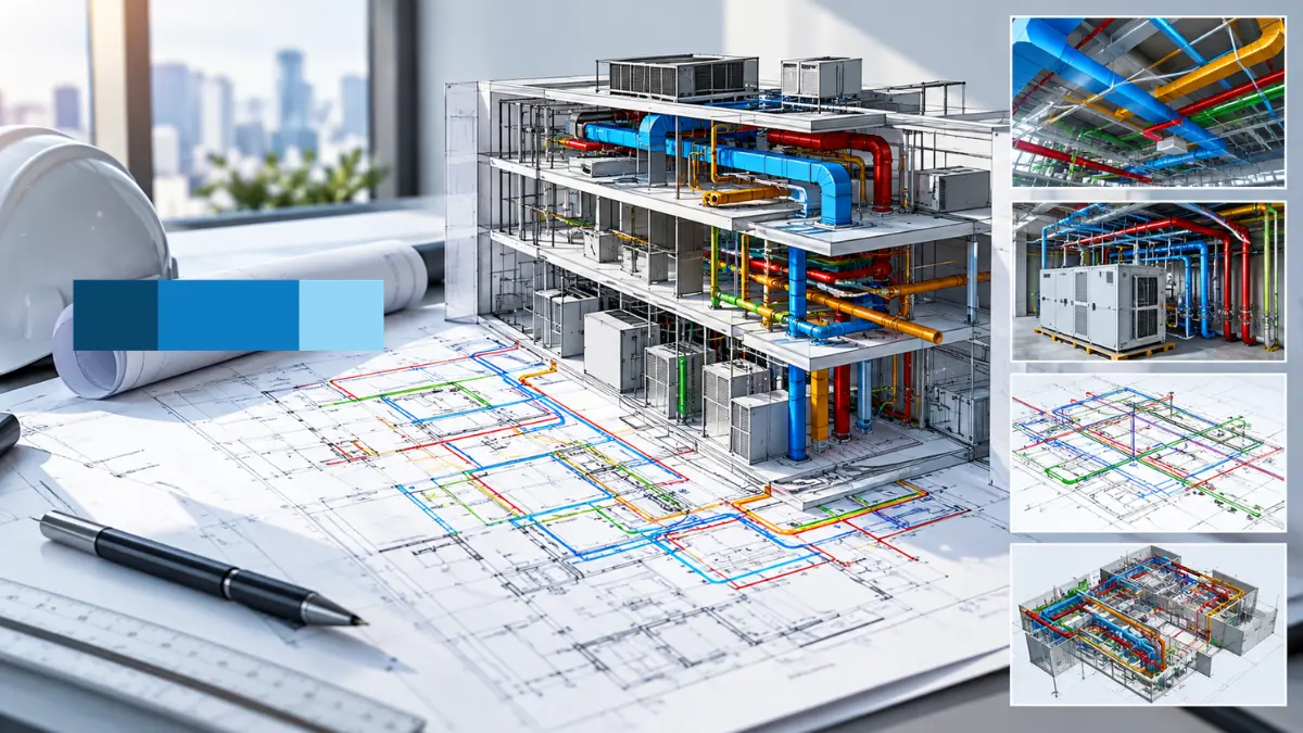
For a commercial construction project to succeed, various mechanical, electrical, and plumbing (MEP) systems must be integrated into the building. MEP drawings provide the required integration. Licensed engineers and architects prepare these drawings, and contractors, subcontractors, and systems installers use them to build the project’s integrated MEP systems. McLine Studios provides coordination services for the U.S. construction industry and helps engineering and architecture firms integrate MEP systems. Being able to interpret MEP drawings helps construction project teams identify potentially costly constructability issues.
This pamphlet provides an overview of MEP drawings. It includes a description of the contents of MEP drawings, different types of construction drawings, and various combinations of drawings used during a project. The pamphlet describes the latest developments in digital drafting and its use in the integration and visualization of building systems. Examples of building systems integration and the use of advanced digital drafting are presented.
What Are MEP Drawings?
MEP drawings demonstrate the routing and installation of building mechanical, electrical, and plumbing systems. Along with architectural and structural drawings, MEP drawings illustrate the design of the building and define the systems and components that provide the function and performance of the completed building.
MEP drawings show the integration of systems with respect to architectural and building construction elements. Systems and components are routed and arranged to perform the functions required to achieve the user’s needs and the intended use of the space. MEP engineering drawings are developed to define the systems to achieve the engineering design. Through interaction with the design and engineering teams, detailed MEP construction drawings are produced to construct the systems and components in the building to achieve the required function.
MEP construction drawings are employed by project participants for a multitude of functions and uses. Estimating the cost to construct the systems and components requires an understanding of the materials to be employed and the sequencing and order of activities by the trades. Installers employ the drawings to fabricate and position the systems and components to the correct building location, and in the proper relationship to other systems and elements. MEP construction drawings define the building systems and provide the basis to achieve the intended use.
What Do MEP Drawings Include?
A complete MEP drawing set consists of three disciplines, and each building system is represented in its appropriate drawing set. There will be modifications to the level of detail, symbols, and abbreviations to coordinate the drawing sets.
Mechanical Drawings
Mechanical drawings depict the systems that move air within a building. They show the equipment, ductwork, and piping that are part of the HVAC drawings. Mechanical drawings typically show the dimensions and location of equipment and ductwork in relation to other equipment, and show clearances to obstructions and access for service and maintenance. On several commercial projects, the mechanical shop drawings provide additional information for the contractor to construct ductwork, such as the size of the ductwork, hanger locations, and fabrication details.
Electrical Drawings
Electrical drawings show how power and lighting services are provided in a building. These drawings show details such as power panel schedules, layout of equipment and branch circuit distribution, layout of lighting and receptacle outlets, switch and control panel layouts, and routing of power and control circuits. Electrical layout drawings show the location of equipment and panels. Construction drawings of these systems, similar to mechanical systems, show the detail needed for completion of rough-in and finish (trim) work. Electrical shop drawings are also prepared by the electrical subcontractor to show the details needed for fabrication, installation, and connection of their scope of work.
Plumbing Drawings
Plumbing drawings encompass domestic water and sanitary systems, vents, and often storm systems. Plumbing layout drawings show the location of fixtures and approximate routes of the piping. Plumbing construction drawings show the size and slope of the piping and the connections to other devices such as water heaters. It is important to coordinate these systems and others early on, because the routing of drain and riser systems is restricted by the final locations of walls and floors.
Types of MEP Drawings Used in Construction
MEP drawings change and evolve as a project progresses. To fully comprehend a project’s drawings, you must identify each type of drawing and understand the many sets of drawings that are created.
MEP design drawings show the engineer’s intent graphically and are developed as part of the design process. MEP construction drawings are generated during the advanced stages of design and reflect the design as it is issued for permit and contractor bidding.
MEP shop drawings are prepared after the contract has been awarded. These drawings show how the systems will be fabricated and built on the job site, including the equipment and materials used for the project. Trade contractors develop these drawings with the assistance of drafting personnel. Shop drawings contain more detailed information about the installation than the drawings prepared by the design professionals.
Before the start of construction, the three technical disciplines (MEP) integrate their design work using models to locate and resolve conflicts. The architectural and structural elements are included in this integration process. As part of the work completed by the owner, design and documentation of the final as-built conditions of the facility are prepared. These documents are used for future renovations. As part of the project, design documents prepared by the design professionals are provided to the local building department to secure a building permit. These documents are presented in the format and level of detail required by the building department.
Why Are MEP Drawings Important for Construction Projects?
Correct MEP drawings help transition a project from design to construction and finally to occupancy. The integration of the mechanical, electrical, and plumbing drawings enables the installation trades to understand and create an installation sequence for their scope of work, instead of discovering potential field conflicts and constraints.
Well thought out drawing further aid in installability. Prior to the completion of the trades’ scope of work, the drawings can potentially identify many conflicts and eliminate the need for rework and field changes. Drawings can be used to define design intent, instead of relying on verbal communication.
For many projects, it is essential that the design team utilize MEP drawings and other clash detection techniques to help eliminate physical and spatial conflicts between the various design systems. For large and/or complicated designs, it is suggested that the design team rely less on traditional design reviews to identify system conflicts and more on building information modeling (BIM) and other 3D coordination and integration techniques. While design integration and review are extremely valuable and help reduce some field issues and conflicts, 3D Modeling and coordination can help ease and reduce many field conflicts and issues.
MEP Coordination and Clash Detection
MEP coordination involves bringing together various elements of mechanical, electrical, and plumbing services, as well as surrounding architecture and structures. It helps in fitting different service elements within the restricted spaces available and resolving potential conflicts among them. It is important to carry out coordination of different building services, as each of them is generally designed and provided by a different engineering consultant. When designed independently, there are reasonable chances that mechanical, electrical, and plumbing systems would contain elements that would be against each other.
MEP coordination drawings resolve this by integrating the different disciplines in a single source, whether it be in the form of a series of printed layer drawings, or more appropriately, in a centralized 3D model. These issues become evident during the design process and/or construction administration. For example, HVAC ductwork routed through a beam, a plumbing riser through an electrical panel location, or interferences between a light fixture and sprinkler heads are types of problems coordinated MEP drawings help to identify.
Using MEP clash detection software, a combined model is created from various discipline models to automatically detect clashes within the model. Through the use of MEP BIM coordination, the teams can identify not only clashes but clearance issues that may impede installation and/or equipment maintenance. This allows the project team to adjust the design before the issues negatively affect constructability and/or installation. Sometimes, clearance issues may result in the need for special tools to perform maintenance on the equipment.
MEP Drawings in AutoCAD and Revit
While CAD and BIM programs can both be used to make MEP drawings, they are not always used for the same purposes.
AutoCAD
AutoCAD is very useful when you need to create 2D drawings from a 3D model. Because not all projects require a full 3D model, AutoCAD is commonly used in projects where the workflow is based on CAD. It is often the case that plans, sections, and details are carefully drafted in AutoCAD. AutoCAD is particularly useful for the documentation of existing building renovations. In such cases, it is common practice to follow the existing drawing standards. Thus, in an established CAD library, drafting of Mechanical, electrical, and plumbing CAD drawings is typically done using AutoCAD. This is the reason why MEP CAD drafting is an important element.
Revit
Revit MEP incorporates architecture and structural design and allows for integration of mechanical, electrical, and plumbing (MEP) design within a unified model. This model-based approach allows for the identification of design conflicts within the model rather than by interpreting 2D drawings. Revit MEP coordination enables the extraction of 3D design data and coordinated construction documentation. Revit MEP drafting and modeling facilitate design changes, as well as the maintenance of design and documentation coordination. The unified approach to design integration supported by Revit MEP modeling facilitates the management of complex and large building construction projects.
While Revit and AutoCAD MEP each have their own project-specific advantages and disadvantages, the appropriate selection of each is based on the experience level and comfort of the design team, as well as the degree of integration of systems within the project.
When Should Contractors Consider Outsourcing MEP Drafting?
Internally, there are limits to the number of drafting teams a company can staff. There are a number of reasons that may cause a company to outsource MEP drafting services. Some of those reasons may include:
- Competing projects limited by the availability of drafting resources.
- Limited time for documentation due to bidding and permitting deadlines.
- Heavily coordinated projects requiring frequent modeling and clash resolutions.
- Repeating shop drawings resulting in a loss of time for more constructive work by the staff.
- Demand for additional support during peak work periods.
- Permanent additional workforce is not required.
MEP drafting services in the US can benefit contractors. It increases production without the need to hire permanent employees. This can be beneficial to firms that work in multiple markets or project types, as the MEP drafting services can also be increased or decreased to meet demand. Engineering and architectural firms outsource drafting and other related services to allow professionals to focus on higher-level building design. Drafting and other related services are a big part of any project, but do not involve making important decisions for the project.
How McLine Studios Supports MEP Documentation
McLine Studios provides outsourcing services for the production of mechanical, electrical, and plumbing (MEP) drawings in the U.S. Our services include support for shop drawing preparation and coordination for U.S. based architects, engineers, contractors, and construction firms.
MEP shop drawing services assist contractors in developing construction shop drawings to construct fabricated mechanical, electrical, and plumbing (MEP) elements. These shop drawings show how the various MEP components would be installed in the project. MEP shop drawings are created to show how a particular MEP component would be fabricated and installed on the project.
In addition to shop drawings, McLine Studios offers a range of services to complement BIM modeling. We provide Revit MEP modeling and MEP BIM modeling, and offer traditional CAD drafting services for the preparation of construction documents in a 2D format. For clients needing MEP set documents for plan review, we format MEP documentation to the required standard for plan submission. We provide multi-disciplinary construction document services for integrating architectural, structural, and MEP drawings to address the needs of multi-disciplinary projects.
The objective is to provide the document control and drafting support required to allow project teams to accurately and efficiently complete project documentation. This will be accomplished without impacting the design decisions made by the project’s engineers and architects.
Final Takeaway
MEP drawings demonstrate how different building systems are interconnected and give details about components of these systems. Design and construction of MEP systems require coordination and integration with other building systems.
Here, the focus is on MEP drawings, their components, how they progress from design drawings to MEP shop drawings, and how MEP coordination assists in avoiding conflicts among different building trades. This information provides the basis for the participants to understand and implement improvements in the documentation of the integrated building design process.
Regardless of the CAD and BIM methodology employed by the designers, the aim is to develop clear, complete, and intelligible documentation for the different building trades. There are many uncoordinated elements in building design and construction. It is the role of the contracting authority to ensure that the designers achieve the required integration. McLine Studios is positioned to provide Revit MEP documentation and CAD shop drawings and drafting services.
Frequently Asked Questions
An MEP drawing is a blueprint used to create various systems within a building. These systems include the building’s mechanical and electrical systems and its plumbing. The drawings are used to construct the systems within the building. Other contractors and construction workers use these drawings to plan the sequencing of the systems within the building.
A set usually contains drawings for the building’s mechanical systems, electrical systems, and plumbing systems. Sometimes, drawings are created to show the relationships between various systems and are included in the drawing set.
MEP drawings shown during the design process of a building reflect the systems’ end-state and how the various systems would integrate within the building. MEP shop drawings shown during the construction process of a building reflect the systems’ end-state, but also include the various materials and equipment used to implement the systems.
Prior to the start of the building construction process, there may be conflicts among the mechanical, electrical, and plumbing systems of the building. The purpose of MEP coordination is to identify and resolve conflicts among these systems as well as conflicts among the building’s systems. This process is done to minimize the number of conflicts among the systems during the construction process.
The Computer-Aided Design (CAD) and Building Information Modeling (BIM) programs are used to create MEP drawings. CAD is used to create traditional 2D drawings. The BIM is used for 3D modeling and drawings.