In the construction industry, MEP drawings are crucial in ensuring the proper design, installation, and coordination of various building systems. These technical drawings serve as blueprints for the intricate network of mechanical, electrical, and plumbing systems essential for a building’s functionality and comfort.
MEP drawings, an acronym for Mechanical, Electrical, and Plumbing drawings. MEP drawings encompass a wide range of documents, each serving a specific purpose and providing detailed information to contractors, engineers, and other professionals involved in the construction process.
From HVAC (Heating, Ventilation, and Air Conditioning) layouts to electrical wiring diagrams, and plumbing riser diagrams to fire protection plans, these drawings are precisely crafted to ensure the seamless integration of all building systems, enabling efficient construction, maintenance, and operation.
In this guide, we’ll understand the MEP drawings and their different types in detail.
What Are MEP Drawings?
MEP drawings are a comprehensive set of technical illustrations depicting a building’s vital systems. Mechanical drawings detail HVAC, piping, and ductwork layouts. Electrical drawings illustrate power distribution, lighting plans, and communication networks. Plumbing drawings showcase water supply lines, drainage systems, and fixture placements.
These drawings are created by specialized drafters, architects, or engineers, these drawings ensure seamless integration and code compliance of a building’s intricate mechanical, electrical, and plumbing infrastructures. MEP drawings serve as crucial references for installation, coordination, and maintenance, facilitating efficient construction and operation of a structure’s essential services.
The Six Different Types Of MEP Drawings
MEP drawings are crucial components of construction and building design. They provide detailed information about the systems that make buildings functional and habitable. Here are six different types of MEP drawings:
Mechanical Drawings
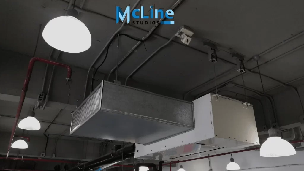
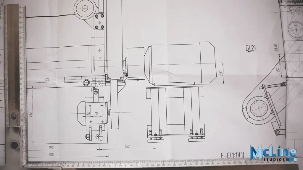
Mechanical drawings are comprehensive plans that detail the heating, ventilation, and air conditioning (HVAC) systems of a building. These drawings provide intricate information about the design, layout, and installation of HVAC equipment and components.
They include specifications for heating units, air handlers, ductwork, ventilation fans, and exhaust systems. Mechanical drawings also indicate the sizing and routing of ducts, including their insulation requirements and support mechanisms.
Additionally, they may incorporate details about equipment clearances, access panels, and maintenance requirements. These shop drawings are essential for ensuring proper airflow, temperature control, and indoor air quality throughout the building.
Electrical Drawings
Electrical drawings are comprehensive plans that illustrate the electrical systems of a building. They provide detailed information about power distribution, lighting, and communication infrastructure.
Electrical drawings specify the location of electrical panels, subpanels, circuits, switches, outlets, and lighting fixtures. They also include wiring diagrams, conductor sizes, and voltage ratings.
Electrical drawings may also incorporate details about emergency backup power systems, such as generators and battery backups, as well as lightning protection measures. These drawings are critical for ensuring that the building’s electrical infrastructure meets safety standards, electrical codes, and the needs of occupants.
Plumbing Drawings
Plumbing drawings are detailed plans that depict the plumbing systems within a building, including water supply, drainage, and sewage systems. These drawings specify the layout and sizing of pipes, fittings, valves, pumps, water heaters, and fixtures such as sinks, toilets, and showers.
They also include information about drainage slopes, venting requirements, and backflow prevention devices. Plumbing drawings ensure that the building’s plumbing design facilitates efficient water distribution, waste removal, and sanitation while complying with plumbing codes and regulations.
They may incorporate details about sustainable water conservation measures, such as low-flow fixtures and graywater recycling systems.
Fire Protection Drawings
Fire protection drawings are specialized plans that focus on the design and installation of fire suppression and detection systems within a building. These drawings detail the layout of fire sprinkler systems, including pipe routing, sprinkler head locations, and hydraulic calculations.
They also specify the placement of fire alarms, smoke detectors, fire extinguishers, and emergency exit signage. Fire protection drawings ensure that the building is equipped with the necessary safety measures to detect and suppress fires effectively, protecting occupants and property from harm.
They may also have details about fire-resistant construction materials, compartmentalization strategies, and egress pathways to facilitate safe evacuation during emergencies.
HVAC Control Drawings
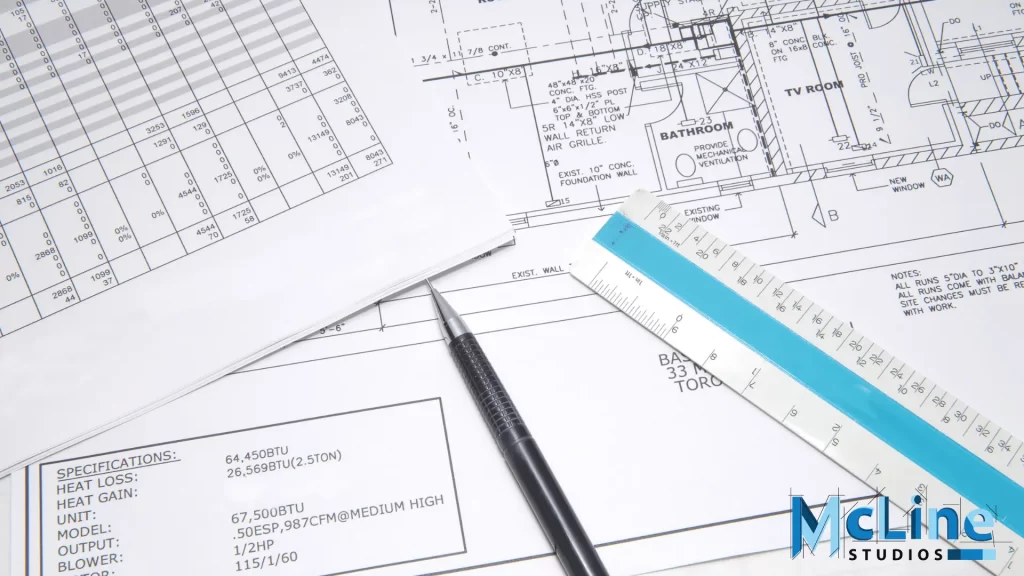
HVAC control drawings are specialized plans that outline the control systems for regulating the operation of HVAC equipment within a building. These drawings specify the layout and programming of thermostats, sensors, actuators, and control panels that monitor and adjust temperature, humidity, and air quality.
They also include sequences of operation, setpoints, and control algorithms for optimizing HVAC system performance. HVAC control drawings ensure that the HVAC system operates efficiently and maintains optimal indoor environmental conditions while minimizing energy consumption.
Additionally, they may incorporate details about integration with building automation systems (BAS) for centralized monitoring and control of MEP systems.
Schematic Diagrams
Schematic diagrams are simplified representations that provide an overview of the MEP systems within a building. These diagrams use symbols, icons, and labels to illustrate the relationships between various components and how they interact.
Schematic diagrams help stakeholders understand the overall layout and operation of MEP systems without getting bogged down in detailed technical drawings. They are valuable tools for design review, coordination among different disciplines, and communication with clients and stakeholders.
Schematic diagrams may encompass multiple MEP systems, showing how they are integrated and interconnected to support the overall functionality of the building.
Key Takeaways
In summary, MEP drawings play a crucial role in the construction industry, serving as a visual representation of the intricate systems that make a building functional and efficient. Whether it’s HVAC plans, electrical schematics, or plumbing layouts, each type of drawing offers unique insights and guidelines for professionals involved in the design, installation, and maintenance of these systems.
With an understanding of the purpose and components of each MEP drawing type within the overall Building Drawings, stakeholders can effectively communicate, collaborate, and execute projects with precision and adherence to industry standards. Ultimately, a comprehensive understanding of MEP drawings ensures seamless integration, optimal performance, and long-term sustainability of a building’s vital systems, contributing to the success of any construction endeavor.
