Every major commercial, institutional, or residential build lives or dies by its blueprints. At McLine Studios, we know that moving from a brilliant architectural concept to a physical, functioning building requires far more than just a good idea. It requires uncompromising precision. That is exactly where multi-disciplinary construction documentation comes into play. We provide the technical backbone that allows developers, architects, and general contractors to execute complex projects without second-guessing the details.
When architectural, structural, mechanical, electrical, and plumbing systems are forced to share the same physical space, conflicts are inevitable unless they are actively managed on paper long before ground is broken. Our specialized teams focus heavily on the mechanics of building. We deliver the kind of integrated documentation packages that give tradespeople clear direction, keep budgets intact, and aggressively reduce the number of change orders that plague modern job sites.
You cannot simply hand a contractor a concept sketch and expect a finished high-rise. You need a deeply coordinated, highly technical set of instructions. Every single sheet in a drawing set carries weight, and our focus is on ensuring that those sheets communicate exactly what needs to be built, where it goes, and how it connects to everything else around it.
Laying the Groundwork with Construction Drawing Services
If you want to understand how a building will actually perform, you have to look at the foundational geometry. The overall architectural layouts establish the permanent structural grid lines, the exact building boundaries, core access corridors, and the specific load-bearing elements that hold everything up. If these foundational drawings are vague or uncoordinated, the men and women on the job site are going to face immediate, cascading delays.
When developers and architectural firms utilize high-quality construction drawing services, they are essentially buying risk mitigation. A well-produced set of architectural plans ensures that every exterior elevation, cross-section, and wall assembly detail complies strictly with local building codes and structural engineering constraints. More importantly, these drawings allow general contractors to perform incredibly accurate material take-offs. When estimators know exactly how much steel, concrete, and framing lumber is required, they can solicit highly competitive, accurate trade bids. This eliminates the inflated pricing that happens when subcontractors have to guess at missing details.
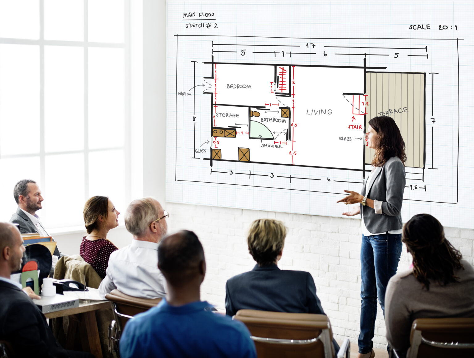
But a building is much more than its exterior shell. The way the internal volume is organized completely dictates how occupants will move through and utilize the facility. Professional interior floor plan drawings dive into the granular data. They call out exact technical dimensions for corridors, define specific partition wall types, generate comprehensive door and window schedules, and map out the exact boundaries of different floor finishes. When a framing crew shows up to lay out metal studs, they rely on these specific drawings to ensure they leave enough clearance for the mechanical systems that will follow them. Without this level of detail, trades end up fighting for space on the floor, which inevitably leads to tearing down and rebuilding work that was already paid for once.
Mastering the Details with Interior Drafting Services
Modern commercial interiors are remarkably complex. Think about a high-end corporate headquarters, a luxury hospitality lobby, or a flagship retail store. These environments require an extraordinary level of technical documentation because the design concepts are highly customized. The core architectural drawings might tell you where the walls are, but it is the interior drafting that focuses on the human scale. This is where we figure out the decorative finishes, the custom joinery, and the specialized architectural elements that actually define the space for the end user.
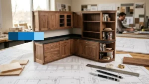
Through focused interior drafting services, drafting professionals take a beautiful rendering and figure out how to actually physically build it. This involves producing highly technical sheets for custom cabinetry, architectural wall paneling, intricate ceiling systems, and complex material transitions like where a polished concrete floor meets a recessed carpeted area. These drawing sets specify precise shop-level dimensions. They call out the exact materials, dictate the mechanical attachment methods, outline the necessary wall backing requirements, and establish the clearances trades need to do their jobs. By locking down these parameters early on, project managers can completely avoid those expensive moments on site where a high-end finish material suddenly collides with a poorly placed air conditioning return.
For truly complex environments, standard drafting simply isn’t enough. That is when specialized interior detailing services take over. Detailing is about the micro-interactions between materials. It involves delivering enlarged section views, plotting out complex junction connection details, and figuring out the structural support framing for heavy architectural features. If a designer wants a massive stone slab to appear as if it is floating off a lobby wall, the detailing team has to figure out the concealed steel armature that makes that illusion possible and safe. When custom features are detailed down to the millimeter before any material is ever cut in a fabrication shop, the approval process speeds up. The trades understand exactly how things go together, and the finished space matches the original design intent without any awkward compromises.
Synchronizing Furniture and Utilities with FF&E Drawings
It is a common mistake to think of furniture as something that just gets moved in at the very end of a project. In commercial, hospitality, and healthcare environments, Furniture, Fixtures, and Equipment (FF&E) represent a massive capital investment that directly impacts the building’s infrastructure. If you do not integrate these dynamic elements directly into the master architectural documentation, you will almost certainly face field conflicts between the freestanding furnishings and the hardwired building utilities.
This is why dedicated FF&E drawings are so critical. These sheets map out the exact physical footprint, outer dimensions, and specific mounting heights for everything from built-in banquette seating and hospital beds to specialized kitchen equipment and decorative lighting chandeliers. More importantly, they map out the weight distribution and the hardwired utility connection points.
Consider a modern corporate conference room. The massive conference table requires power, data, and audio-visual connectivity directly underneath it. If the FF&E plan is perfectly coordinated with the electrical plan, the concrete contractors know exactly where to place the floor core boxes before the concrete is even poured. If that coordination doesn’t happen, the contractor has to bring in equipment to core through finished concrete later, which is loud, messy, expensive, and risks hitting structural rebar. Coordinating these elements early in the drafting cycle guarantees that the site is fully prepared for the equipment the moment it arrives.
The Evolution of a Drawing Set: Schematic Design and Beyond
Nobody generates a perfect, buildable set of plans on the first try. Creating complete, error-free building packages is a highly structured, iterative process. It moves systematically from high-level spatial blocking down to granular, buildable instructions. Each distinct phase of this development serves a very specific purpose in refining the design intent, verifying that it can actually be built, and resolving technical bottlenecks.
The technical documentation lifecycle always starts with schematic design. During this early stage, the client’s space programs, raw spatial concepts, and architectural ideas are translated into preliminary line drawings. We look at overall site master plans, massing studies, and early floor layouts. This phase is all about establishing the boundaries. What is the project’s overall scale? What is the building footprint? What does the primary structural grid look like, and how will people circulate through the space? Engaging in multi-disciplinary review during this preliminary stage is incredibly valuable. It helps teams identify major spatial conflicts and glaring zoning or code challenges long before significant time and financial resources are spent on full-scale drafting.
Once the initial schematic framework is locked in and approved by the owner, the project graduates into Design Development. This is the transition stage where preliminary spatial ideas are expanded into real, physical technical systems. This is where the heavy lifting happens. Material specifications are nailed down. Structural columns get their actual engineered sizes. Mechanical duct pathways are routed, plumbing risers are located, and specific wall assembly types are chosen. The drawings progress rapidly here. They move from simple single-line spatial outlines to fully dimensioned, multi-layered drawing packages. We start incorporating the hard data from the structural and MEP (Mechanical, Electrical, and Plumbing) engineers, blending it with detailed architectural finish schedules.
The culmination of all this iterative work results in comprehensive CAD construction drawings. These are the final, fully realized, coordinated building sets that go out for contractor bidding and physical job site execution. These detailed sets bring together the complex, often conflicting inputs from architectural designers, structural engineers, and MEP specialists into one single, synchronized set of plans. Producing these in a strict CAD environment guarantees exact geometric accuracy. It enforces standardized layer naming conventions and precise scale management and allows for seamless digital file sharing across all project stakeholders, from the general contractor in the site trailer to the steel fabricator in the shop.
Navigating Municipal Approvals with Permit Set Drawings
Before a single shovel hits the dirt, comprehensive building plans have to pass intense technical reviews by local municipal building departments, fire marshals, and zoning boards. If your drawings get kicked back at this stage, the delays can be devastating. Protracted permitting delays disrupt subcontractor availability, destroy project delivery schedules, and drastically increase carrying costs for the developer.
Engineered permit set drawings are built specifically to survive this scrutiny. They are structured to demonstrate absolute compliance with national and local building codes, municipal zoning bylaws, strict fire safety mandates, ADA accessibility guidelines, and structural integrity standards. These specialized sheet sets contain highly detailed life-safety plans, occupancy load calculations, and mapped-out emergency egress pathways. They show structural load paths, energy compliance certificates, and fully annotated site utility connections. By structuring these sets with incredibly clean sheet layouts, complete code references, and transparent technical annotations, we help municipal review officers process the applications efficiently. The goal is to minimize formal revision requests, answer the reviewer’s questions before they even have to ask them, and secure the building permits right on schedule.
Capturing Reality with As-Built Drawings
It is important to remember that not every construction project involves an empty plot of land. Major renovations, historic restorations, adaptive reuse developments, and commercial tenant fit-outs make up a massive portion of the industry. These projects require complete, highly accurate data regarding the existing structural conditions before any new interior design work can safely commence. You cannot design a new layout if you do not know exactly where the existing concrete columns actually sit.
Reliable as-built drawings capture the physical, dimensional reality of an existing structure. These are not the original design plans from twenty years ago; those are rarely accurate to what was actually built. Instead, these drawings document field-verified dimensions. They show actual structural column placements, existing HVAC ductwork paths, true ceiling heights, current utility access points, and the real locations of partition walls. Utilizing accurate, field-verified historical drawings protects project managers and site engineers from encountering nasty surprises during the demolition or initial framing phases. Having a fully updated reference set ensures that new interior layouts, structural retrofits, and updated mechanical systems integrate cleanly with the existing building structure without causing unexpected clashes.
The Mechanics of Multi-Disciplinary System Coordination
Modern buildings are not just walls and roofs; they are incredibly complex machines composed of tightly integrated structural, mechanical, and architectural systems. Achieving accuracy out in the field demands aggressive multi-disciplinary coordination. The goal is to ensure that architectural features, heavy structural steel frames, and bulky mechanical infrastructure all coexist without fighting for the same spatial volume.
A massive percentage of on-site change orders and construction delays stem directly from spatial conflicts between different trade plans. Imagine heavy HVAC ductwork running directly through a structural steel beam, or a primary plumbing waste stack intersecting with a high-voltage electrical cable tray. If these issues aren’t caught on paper, they are caught on the job site. When that happens, work stops. Requests for Information (RFIs) are filed. Engineers scramble to find a workaround, materials are wasted, and timelines slip.
High-level technical coordination synchronizes all of these different architectural, structural, and MEP plans into a single unified workspace. By resolving these spatial clashes digitally during the drafting stage, we keep job site teams working efficiently. We prevent the friction that naturally occurs between different trades when they are fighting for space in a tight ceiling plenum, and we save developers thousands of dollars in material waste and field rework.
Standardization and the Ability to Scale
The visual presentation of technical documentation is just as important as the data it contains. Precision extends directly to graphic presentation, standardized layering structures, strict dimensioning protocols, and clean sheet title blocks. Maintaining uniform drafting standards across every single discipline sheet ensures that a field supervisor reading a plan on a tablet in the bright sun can understand it with complete clarity. Consistent line weights, uniform symbol libraries, clear detail callouts, and highly organized sheet indexes streamline information retrieval on fast-paced job sites. When a contractor can find the information they need in seconds, the whole project moves faster.
Furthermore, large-scale commercial developments, multi-family housing complexes, and sprawling healthcare campuses require massive volumes of technical sheets produced under very demanding timelines. Achieving high output while maintaining strict accuracy demands highly structured production workflows, multi-tiered quality control checks, and robust CAD management protocols. A disciplined, highly scalable drafting framework enables project teams to expand drawing production rapidly to meet aggressive deadlines without ever sacrificing technical accuracy or real-world constructability.
Commitment to Technical Excellence
Ultimately, clear visual communication, technical precision, and seamless multi-disciplinary alignment form the absolute foundation of every successful construction project. From the earliest spatial blocking concepts created during the schematic phases to the final, field-verified drawings utilized by facility managers years after the building opens, high-quality technical documentation protects the timeline, controls the budget, and honors the architect’s original design intent.
At McLine Studios, we are deeply committed to providing world-class drafting and documentation solutions. Our services empower architects, structural engineers, real estate developers, and general contractors to go out and build with absolute confidence. Our rigorous attention to detail, strict adherence to global CAD standards, and deep technical capabilities ensure that every drawing package we deliver satisfies the highest industry standards. By partnering with a dedicated team of documentation specialists, industry leaders can transform their most complex architectural visions into clearly defined, error-free, and highly buildable realities that will stand and perform reliably for generations to come.