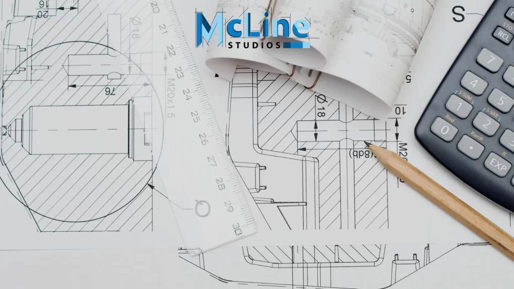
Steel shop drawings are a critical component of any structural steel project. They serve as detailed instructions for the fabrication and installation of steel members, ensuring that the final structure conforms to the design specifications. Whether you’re an architect, engineer, contractor, or fabricator, having a solid understanding of these drawings is essential for successful project execution.
This comprehensive guide aims to provide you with an expert’s perspective on steel shop drawings. We’ll dive into the intricacies of these technical documents, exploring their purpose, components, and the collaborative process involved in creating steel shop drawings.
What Are Steel Shop Drawings?
Steel shop drawings are a crucial component in the construction process involving structural steel elements. They are detailed drawings prepared by the steel fabricator, based on the structural design drawings provided by the architect or engineer.
These shop drawings serve as a comprehensive guide for the fabrication and installation of steel members, ensuring precision and accuracy during construction.
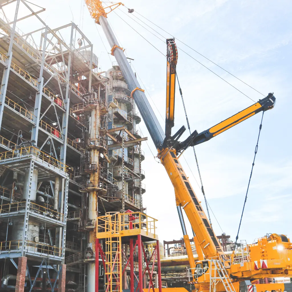
Shop drawings typically include detailed information such as dimensions, connection details, bolt patterns, weld sizes, and other critical specifications for each steel component.
They also provide instructions for the proper assembly and erection sequence, ensuring the steel members are installed correctly on-site. The project’s structural engineer precisely reviews and approves these drawings before fabrication begins.
Purpose Of Steel Shop Drawings
Steel shop drawings serve as detailed plans and instructions for the fabrication and installation of steel components in construction projects. These drawings are essential for ensuring accuracy, efficiency, and safety throughout the entire steel fabrication process.
The primary purpose of steel shop drawings is to provide precise information regarding the dimensions, connections, materials, and specifications of steel structures. They translate the design intent of engineers and architects into actionable instructions for fabricators and construction teams.
Steel shop drawings aid in reducing errors and inconsistencies during fabrication and erection by detailing every aspect of the steel components, including their placement, orientation, and connection specifics.
Moreover, steel shop drawings facilitate communication and coordination among various stakeholders involved in a construction project, including architects, engineers, steel fabricators, and contractors. They serve as a reference point for quality control, ensuring that the final steel elements meet the required standards and specifications.
Components Of Steel Shop Drawings
Steel shop drawings are detailed drawings prepared by steel fabricators or detailers that provide the necessary information for the fabrication and installation of steel components in construction projects. The components of steel shop drawings typically include:
- General Information: This section includes project details such as the project name, location, drawing number, date of issue, and the name of the fabricator or detailer.
- Cover Sheet: This sheet provides an overview of the drawing set, including a list of drawings, revision history, and any special notes or instructions.
- Structural Plans: These drawings show the overall layout and dimensions of the steel components within the structure. They include plan views, elevations, and sections detailing the steel framing, columns, beams, and connections.
- Detail Drawings: Detail drawings provide enlarged views of specific steel connections, joints, and components. They include dimensions, material specifications, welding symbols, and other pertinent information necessary for fabrication and installation.
- Material List: This is a detailed list of all the materials required for the steel components, including types of steel, sizes, lengths, quantities, and any other relevant information.
- Connection Design: Detailed drawings and calculations for connections between steel members, including welds, bolts, and other fasteners. This section may include diagrams, schedules, and specifications for connection details.
- Anchor Bolt Plans: Plans showing the layout, size, and embedment depth of anchor bolts used to secure steel components to the foundation or supporting structure.
- Erection Plans: These drawings provide instructions for the assembly and erection of steel components on-site, including lifting details, bracing requirements, and sequence of erection.
- Quality Control Documentation: Documentation outlining quality control procedures, inspections, and certifications required for the fabrication and installation of steel components.
Who Prepares Steel Shop Drawings?
Steel shop drawings are typically prepared by the steel fabricator or the steel detailer, who is responsible for translating the structural engineer’s design into detailed fabrication and erection instructions for the steel components.
The steel detailer’s primary role is to create shop drawings that provide precise information on the size, shape, and dimensions of the individual steel members, as well as the locations and specifications for connections, holes, and other details necessary for the fabrication and installation of the steel structure.

These shop drawings serve as a critical link between the structural engineer’s design and the actual fabrication and erection processes. They ensure that the steel components are accurately manufactured and assembled according to the design specifications, ensuring the structural integrity and safety of the finished structure.
The steel detailer works closely with the structural engineer, architect, and fabricator to ensure that the shop drawings accurately reflect the design intent and comply with all relevant building codes and standards.
They also coordinate with other trades, such as concrete, mechanical, and electrical, to ensure that the steel structure integrates seamlessly with the overall building design.
Once the shop drawings are approved by the structural engineer, they are used as a guide by the fabricator to cut, drill, and assemble the steel components, and by the erector to properly install and connect the steel members on site.
Key Takeaway
In wrapping up, it’s clear that steel shop drawings are the unsung heroes of the construction world. They’re not just blueprints; they’re the guiding light for fabricators, erectors, and engineers, ensuring that every bolt and beam is in the right place.
These drawings don’t just save time; they’re crucial for avoiding costly mistakes and keeping projects on track. And with technology like Building Information Modeling (BIM) on the rise, these drawings are becoming even more vital for seamless collaboration among teams.
