Behind every building, whether it is a skyscraper or a cozy home, lies a set of intricate plans that bring the design to life. These plans, known as architectural drawings, are far more than simple sketches. They are the visual language that guides a building from an idea to reality.
Architectural drawings are the detailed blueprints architects create to define every part of a building. They provide a clear representation of the layout, structure, and design elements. Without them, the entire process would be chaotic and uncertain.
But these drawings do not just show where walls and doors go. They play a crucial role in making sure the building is safe, functional, and meets all the necessary codes and regulations. In this article, we will explore the common types of architectural drawings.
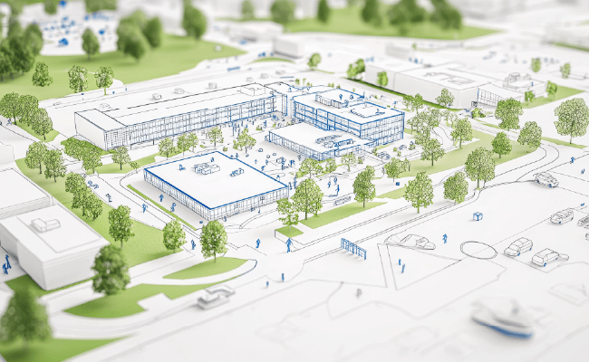
Site Plans
A site plan provides an overview of the land where the building will be constructed. It shows the boundaries of the property, surrounding features, and the placement of the building on the site. Site plans also include roads, pathways, landscaping elements, parking spaces, and utilities such as water and electricity lines.
Why It Matters: A site plan helps determine how the building interacts with the surrounding environment. It also make sure compliance with zoning laws and regulations, helping the project stay within the legal boundaries of the site.
Use case: Site plans are used when applying for zoning permits, laying out the property’s boundaries, or planning infrastructure like drainage and access roads.
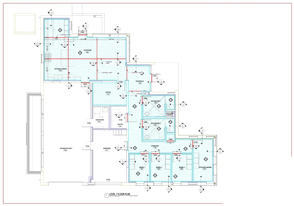
Floor Plans
Floor plans are among the most essential architectural drawings. They show the layout of each floor of the building, including walls, doors, windows, and the dimensions of each room or space. These floor plans give a detailed view of how people will move through the building and how spaces are divided for various functions.
Why It Matters: Floor plans help so that the building functions properly by organizing spaces logically.
Use Case: Floor plans are crucial when planning the interior layout, submitting permit applications, and guiding construction teams on the exact placement of walls and rooms.
Elevation Drawings
Elevation drawings represent the exterior of the building as viewed from different angles, typically front, rear, left, and right. These drawings show the building’s facade, including details like window placement, door design, and material choices. They also indicate the height of different parts of the building.
Why It Matters: Elevations provide a clear idea of the building’s appearance. They help so that the building aligns with the desired aesthetic and that it fits well with the surrounding environment. These drawings are also critical for obtaining approvals from zoning and planning authorities.
Use Case: Elevations are used in design presentations, permit applications, and by contractors to understand how the building will look once complete.
Section Drawings
A section drawing is like slicing through a building to show its internal structure. It reveals the relationship between floors, ceilings, walls, and other components. Sections also show the heights of different rooms and levels, as well as key structural elements like beams and columns.
Why It Matters: Sections are crucial for understanding how different parts of the building fit together vertically. They provide a clear picture of the internal layout and structure.
Use Case: Section drawings are used to review how the vertical elements of a building interact, check structural integrity, and assist contractors during construction.
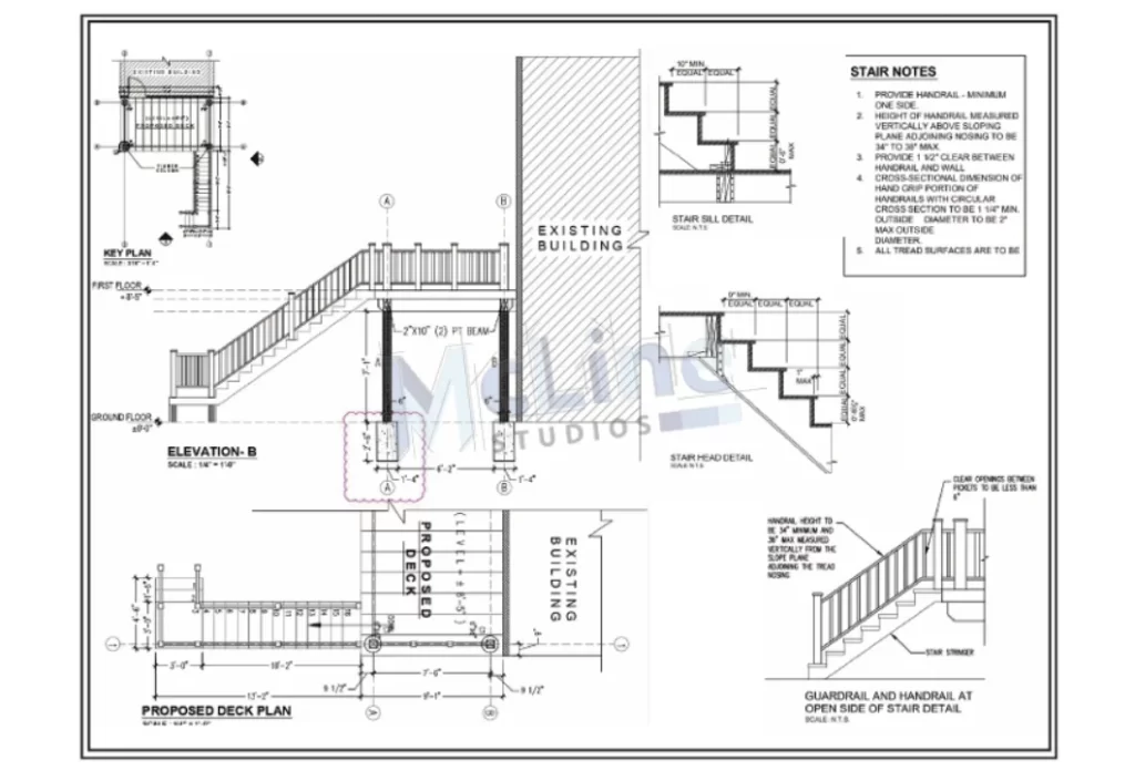
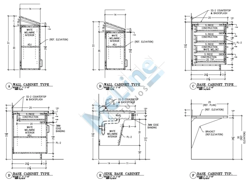
Detail Drawings
Detail drawings zoom in on specific elements of the building, such as staircases, joints, windows, or doorframes. These drawings focus on the finer points of construction, providing in-depth information about how certain parts of the building should be constructed.
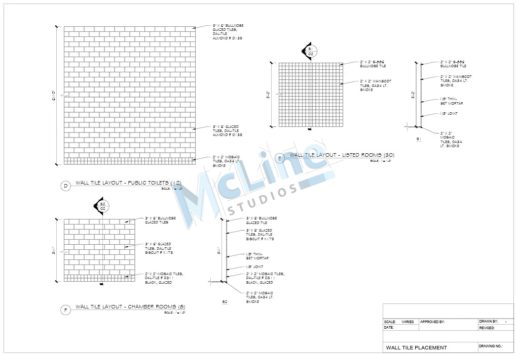
Why It Matters: Details drawings help contractors understand how to properly assemble the building’s components, avoiding mistakes that could lead to structural problems or delays.
Use Case: Detail drawings are used in the construction phase to accurately build specific components, such as window frames, wall joints, and roofing systems.
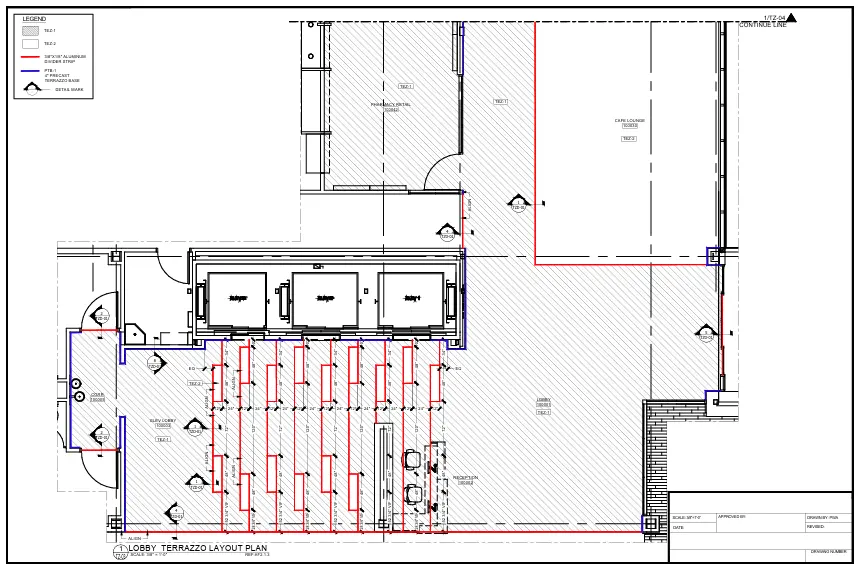
Reflected Ceiling Plans
A reflected ceiling plan shows the ceiling layout of a building as if the ceiling were reflected in a mirror. This drawing includes the placement of lighting fixtures, air conditioning vents, sprinkler systems, and other ceiling-mounted elements.
Why It Matters: This drawing helps so that all ceiling elements are properly planned and coordinated. It helps avoid issues with light placements, ventilation, or fire safety systems. It makes the space more functional and meets all necessary regulations.
Use Case: Reflected ceiling plans are used by electricians, HVAC specialists, and other contractors to install ceiling elements during construction.
Roof Plans
Roof plans show the layout and design of the roof. They include details like slopes, drainage, and roofing materials. Roof plans also highlight features like skylights, chimneys, or any mechanical systems installed on the roof.
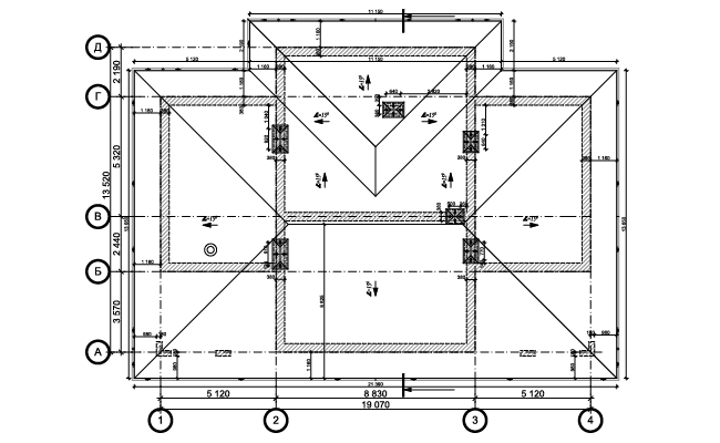
Why It Matters: Roof plans are essential for constructing a roof that is both functional and weather-resistant. Proper drainage and slope are critical to prevent water damage and other issues.
Use Case: Roof plans are used by roofing contractors and engineers to construct the roof and confirm it is built according to specifications.
Electrical and Plumbing Plans
These plans show the layout of electrical wiring, outlets, switches, and lighting fixtures, as well as plumbing systems like water pipes, drains, and fixtures. Electrical and plumbing plans are crucial for integrating these systems into the building design.
Why It Matters: These drawings help avoid conflicts between different building systems and make sure the electrical and plumbing setups are safe and functional. They also help builders follow local building codes.
Use Case: Electrical and plumbing plans are used by contractors and specialists so that the electrical and plumbing systems are installed correctly and safely.
Structural Drawings
Structural drawings focus on the building’s framework, its foundations, beams, columns, and load-bearing elements. These drawings provide the specifications for constructing a safe and solid structure, making sure the building can withstand natural forces like wind and earthquakes.
Why It Matters: These drawings are essential for the building’s stability and safety. Structural integrity is a top priority in any construction project, and these drawings help guide the construction of the building’s framework.
Use Case: Structural drawings are used by engineers and contractors to build the framework of the building and verify that it is solid and safe.
Landscape Plans
Landscape plans show the design of outdoor spaces, including gardens, lawns, walkways, and trees. They also provide details on how the land will be graded to handle water runoff and other environmental factors.
Why It Matters: Landscape plans are critical for designing outdoor spaces that complement the building. They also manage the building’s environmental impact by ensuring effective drainage and the integration of greenery.
Use Case: Landscape plans are used during the construction of outdoor spaces and are helpful for local municipalities during approval processes for land development.
As-Built Drawings
As-built drawings are the final set of drawings that reflect the actual structure after construction is complete. These drawings capture any changes that occurred during the building process, updating the original plans to reflect the real, built environment.
Why It Matters: As-built drawings provide an accurate record of the finished project, which is essential for future renovations, repairs, or expansions. They also serve as a reference if issues arise after construction.
Use Case: As-built drawings are used for renovation projects, future repairs, or for compliance with regulations that require updated documentation of the building’s design.
Who Creates Architectural Drawings?
Architectural drawings are created by a team of professionals who each bring their expertise to the project.
- Architects are the primary creators of architectural drawings. They design the building and its layout, focusing on both functionality and aesthetics. Architects make floor plans, site plans, and elevations to show the overall design of the building.
- Draftsmen (or drafters) work closely with architects to turn their ideas into detailed technical drawings. They use software to guarantee all measurements and details are accurate for construction.
- Structural engineers are responsible for the safety of the building. They create drawings for the foundation, beams, and load-bearing elements, making sure that the building can withstand forces like wind and earthquakes.
- MEP engineers focus on the building’s mechanical, electrical, and plumbing systems. They create drawings for systems such as air conditioning, lighting, and water supply.
Wrapping Up: The Importance of Architectural Drawings
In short, architectural drawings are key to every construction project. They act as a roadmap, guiding the process from start to finish. These drawings help make sure the building is safe, functional, and matches the design. Architects, engineers, draftsmen, and other experts work together to create these plans, each focusing on different parts of the building, such as structure, systems, and design.

From room layouts to the placement of walls, windows, and plumbing, architectural drawings provide clear instructions for every detail. They help avoid mistakes during construction and make sure everything follows safety guidelines and local regulations.
In the end, architectural drawings are the foundation of any building project. They keep everyone involved on the same page and help turn ideas into reality. Without these drawings, constructing a building would be almost impossible.